Guide vane assembly

A technology of guide vanes and components, applied to pump components, engine components, components of pumping devices for elastic fluids, etc., can solve problems such as tedious manufacturing of holes, low elastic travel of clamping sleeves, etc., and achieve simple cost The effect of manufacturing and simplifying the structure

Inactive Publication Date: 2017-12-05
SIEMENS AG
View PDF5 Cites 3 Cited by
  • Summary
  • Abstract
  • Description
  • Claims
  • Application Information

AI Technical Summary

Problems solved by technology

These clamping sleeves have a bore that is open laterally, but the manufacture of this bore is rather cumbersome
Another disadvantage is the relatively low spring travel of the clamping sleeve

Method used


Image

  • Guide vane assembly
  • Guide vane assembly
  • Guide vane assembly

Examples


Embodiment Construction

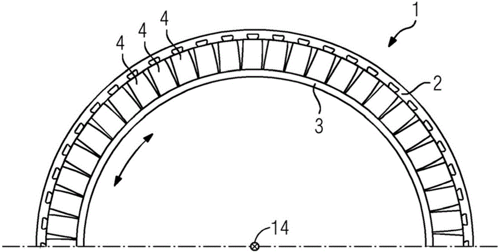
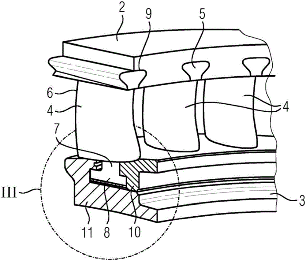
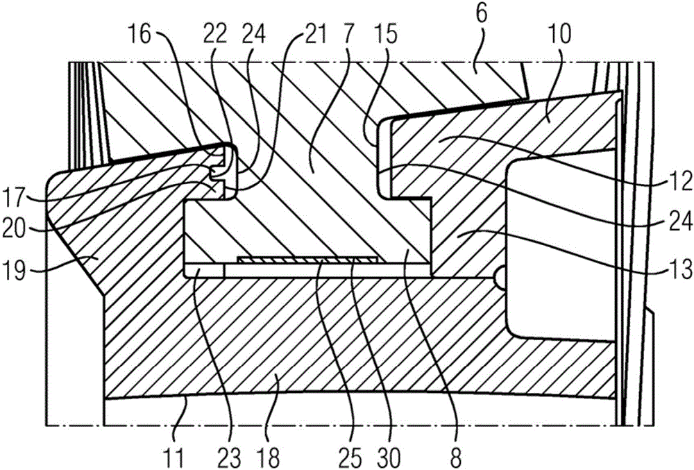
[0030] Figure 1 to Figure 15 Shown is a guide vane assembly 1 or parts thereof according to one embodiment of the invention. The guide vane assembly 1 includes an outer ring 2 as main components, an inner ring 3 and a plurality of guide vanes 4, these guide vanes extend between the outer ring 2 and the inner ring 3, and these guide vanes respectively have stationary vane roots 5, static vanes The vane 6 and the vane head 8, the vane root 5 is fastened at the outer ring 2, the vane 6 extends between the outer ring 2 and the inner ring 3, and the vane head 8 passes through the vane joint 7 is connected with the stator blade 6 and has a hook structure, and the stator blade head 8 is fastened at the inner ring 3 .

[0031] The outer ring 2 and the inner ring 3 are arranged concentrically in a known manner on a virtual machine axis 14 , which is used as the reference axis for the terms “radial” and “axial”.

[0032] A plurality of vane root receiving grooves 9 are provided along...


PUM


Abstract

The invention relates to a guide vane assembly (1) comprising at least partially resilient brackets (25; 31; 34), each of which has some tolerance between a web (7) of a guide vane (4) and an inner ring (3) of the guide vane assembly (1), the web (7) being located between a boot (8) and an airfoil (6) of the guide vane (4).

Description

technical field [0001] The present invention relates to a guide vane assembly, which comprises an outer ring, an inner ring and a plurality of guide vanes extending between the outer ring and the inner ring, the guide vanes each have: Fixed at the outer ring, a stator vane, extending between the outer ring and the inner ring, and a stator blade head, which is connected to the stator blade by a stator blade joint and is of a hook configuration, the The vane head is fastened at the inner ring, wherein the inner ring is composed of at least a first inner ring element and a second inner ring element, the first inner ring element has a plurality of receiving grooves through which the vane tabs extend These receiving grooves, and the first inner ring member and the second inner ring member define at least one receiving space therebetween, the receiving space is radially inwardly coupled to the receiving grooves, and the vane head is received in this containment space. Background ...

Claims


Application Information

Patent Timeline
IPC IPC(8): F01D9/04F01D25/24
CPCF01D9/042F01D25/246F04D29/542F04D29/644
Inventor M·德赖曼E·波尔施A·施尔玛赫D·策尔默
Owner SIEMENS AG
Why Eureka
Try Eureka