Electronic mechanical drive-by-wire brake

A brake-by-wire and electromechanical technology, applied in the types of brakes, axial brakes, brake components, etc., can solve problems such as complex brake structure, large installation size, and difficult control of braking efficiency

Active Publication Date: 2017-12-01
ZHEJIANG NORMAL UNIVERSITY
View PDF8 Cites 5 Cited by
  • Summary
  • Abstract
  • Description
  • Claims
  • Application Information

AI Technical Summary

Problems solved by technology

However, the existing electromechanical braking system often lacks the function of automatic adjustment of the brake gap in the brake part, which causes the problem that the efficiency of the brake actuator changes indeterminately when the external environment changes and the friction lining is worn. Braking efficiency control brings certain difficulties
At the same time, most brakes have problems such as complex structure and large installation size.

Method used


Image

  • Electronic mechanical drive-by-wire brake
  • Electronic mechanical drive-by-wire brake
  • Electronic mechanical drive-by-wire brake

Examples


Embodiment Construction

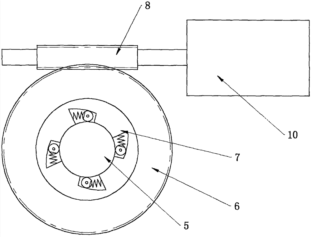
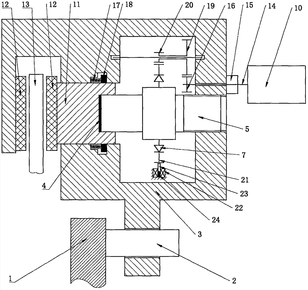
[0018] Reference attached figure 1 And attached figure 2 , an embodiment of the present invention will be described in detail.

[0019] Such as figure 1 As shown, an electromechanical brake by wire includes a brake caliper body (3) that can move on a guide pin (2), and the guide pin (2) is fixed on a brake caliper bracket (1). There is a brake disc (13) in the jaw of the brake caliper body (3), and there are friction discs (12) on both sides of the brake disc (13), one is mounted on the brake caliper body (3), and the other is mounted on the piston (11), the piston (11) is installed on the brake caliper body (3) through the sealing ring (9), and there is a relatively large friction force between the contact surface of the sealing ring (9) and the piston (11), when the piston ( 11) When the displacement is within the elastic deformation range of the sealing ring (9), there is no relative movement between the contact surfaces of the sealing ring (9) and the piston (11). The...


PUM


Abstract

The invention relates to an electronic mechanical drive-by-wire brake. The electronic mechanical drive-by-wire brake comprises a motor, a transmission mechanism, a one-way clutch, a screw, a piston, a friction limiting device and the like. The motor drives the one-way clutch to rotate through the transmission mechanism, the one-way clutch is combined to drive the screw to rotate, the threaded transmission mechanism separately drives the piston and a brake caliper body to move in reverse directions, and a friction plate is pressed with same force from the two sides of a brake disc, so that the efficient brake effect is realized. The electronic mechanical drive-by-wire brake is simple in structure, is reliable in work, is high in braking efficiency, can automatically regulate a brake gap, compensates influences caused by friction plate abrasion, simplifies design of a control system, and can be used for travelling brake and parking brake.

Description

technical field [0001] The invention relates to the field of brakes, in particular, it can replace the existing floating caliper disc hydraulic brakes, realize friction discs clamping the brake discs from both sides with the same pressure in an electronically controlled manner, and at the same time realize adjustable brake clearances , a wire-controlled mechanical brake with adjustable braking strength, in particular an electromechanical wire-controlled brake. Background technique [0002] Brake-by-wire technology is a new type of braking technology that has emerged in recent years. It does not rely on mechanical or hydraulic connections between the brake and the brake pedal. The control system receives the information from the sensor to control the motor to work. Stable and reliable brake control. At present, there are mainly two types of electronic hydraulic braking system (EHB) and electromechanical braking system (EMB). The brake-by-wire system is conducive to the opti...

Claims


Application Information

Patent Timeline
Patent Type & Authority Applications(China)
IPC IPC(8): F16D55/224F16D65/16F16D65/38F16D121/04F16D121/14F16D121/24
CPCF16D55/224F16D65/16F16D65/38F16D2065/386F16D2121/04F16D2121/24F16D2121/14Y02E10/72
Inventor 董颖常占辉
Owner ZHEJIANG NORMAL UNIVERSITY
Why Eureka
Try Eureka