vacuum valve

A vacuum valve and valve seat technology, applied in valve details, valve devices, sliding valves, etc., can solve the problems of high cost of vacuum valves, unit consumption of driving components and guiding components, etc., and achieve the effect of simple cost

Active Publication Date: 2019-05-10
VAT HLDG AG
View PDF16 Cites 0 Cited by
  • Summary
  • Abstract
  • Description
  • Claims
  • Application Information

AI Technical Summary

Problems solved by technology

A disadvantage of the device disclosed by this document is the relatively complex construction of the unit with drive element and guide element, which results in an expensive vacuum valve
It is also difficult for this vacuum valve to selectively adopt different types of drive devices.

Method used


Image

  • vacuum valve
  • vacuum valve
  • vacuum valve

Examples


Embodiment Construction

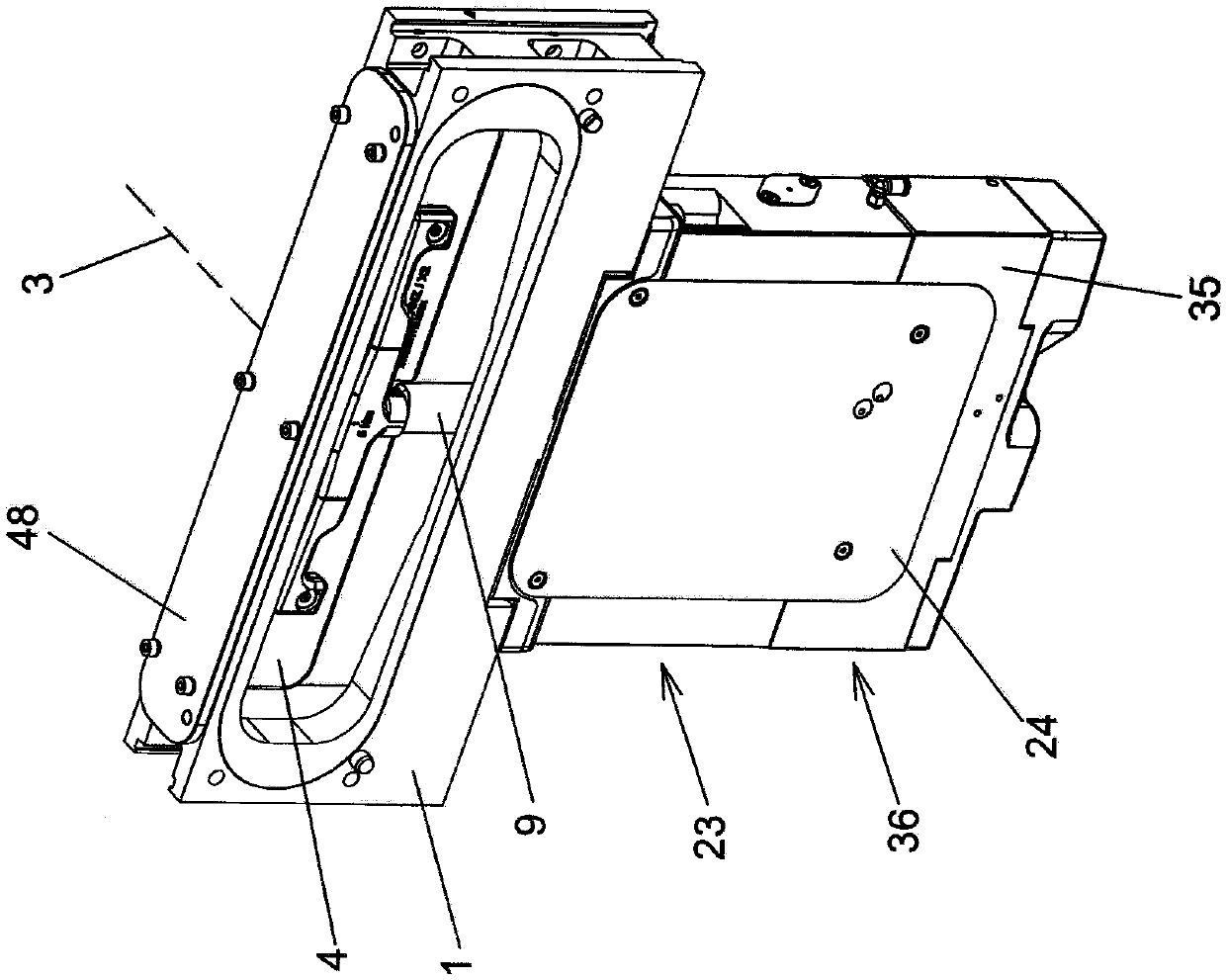
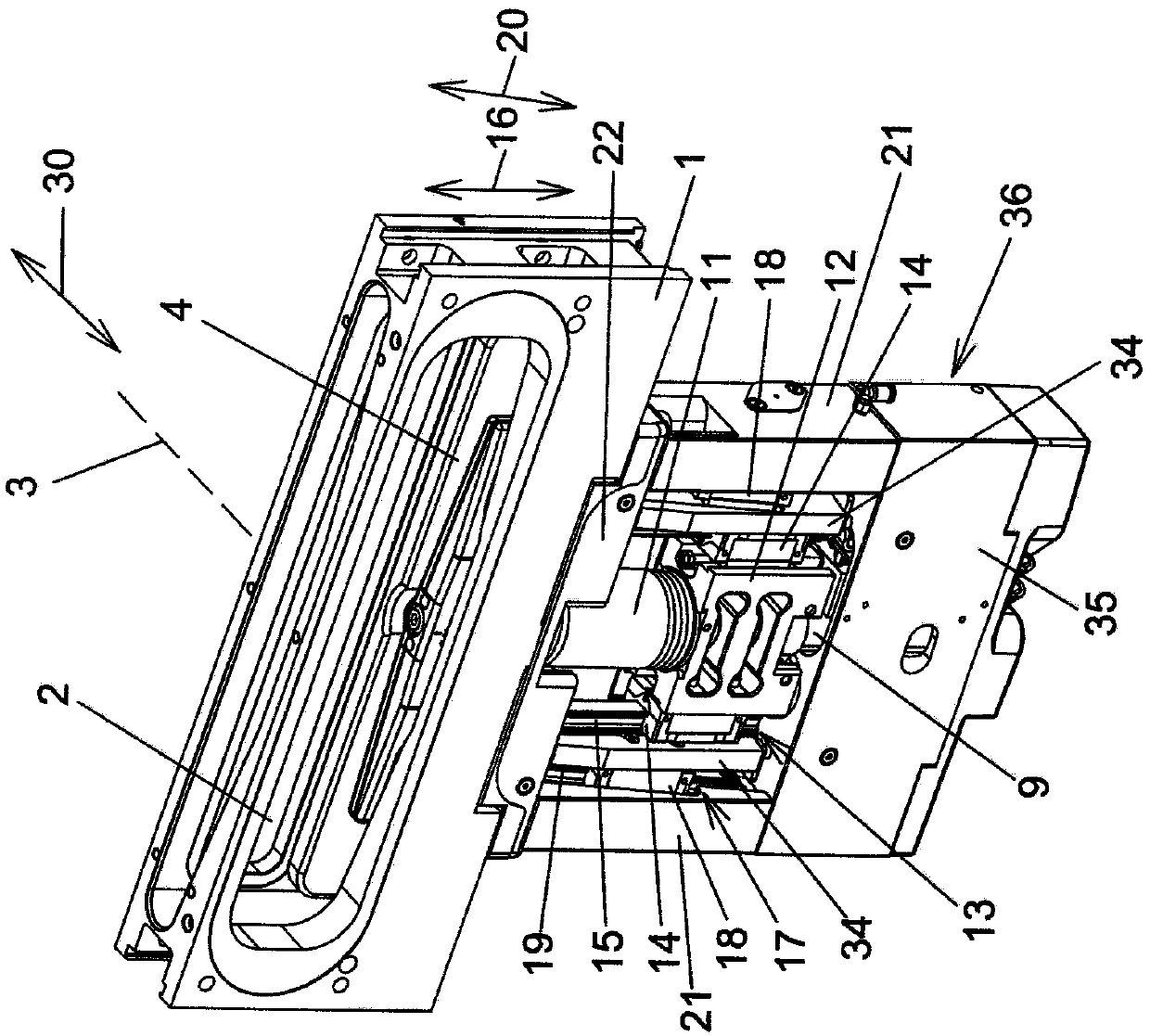
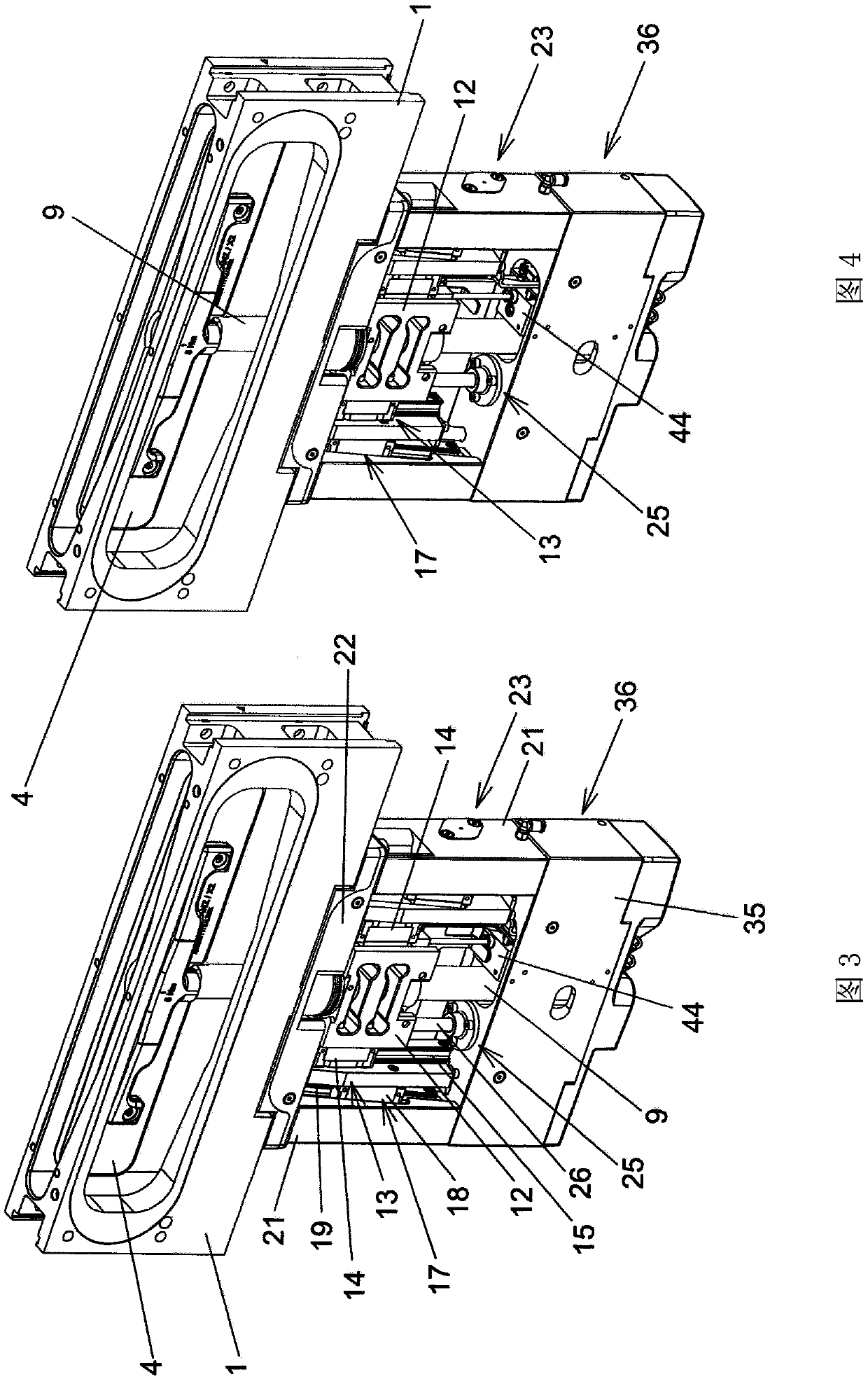
[0036] An exemplary embodiment of a vacuum valve according to the invention is shown in the drawing.

[0037] The vacuum valve has a valve body 1 with a wall having a valve opening 2 with an axis 3 . In the closed state of the vacuum valve, the valve opening 2 is closed by an in particular plate-shaped closing member 4 , which is then in its closed position. In the closed position of the closing member 4 , it is pressed against a valve seat 5 , which surrounds the valve opening 2 on the side facing the closing member 4 . In the open state of the vacuum valve, the closing member 4 releases the valve opening 2 and the closing member 4 is then in its open position. The movement of the closing member 4 between the closed position and the open position takes place via an intermediate position in which the closing member covers the valve opening 2 as viewed on the axis 3 of the valve opening 2, but from the valve Remove (= disengage) from seat 5.

[0038] In order to seal between...


PUM


Abstract

A vacuum valve comprising a valve body (1) having a valve opening (2) surrounded by a valve seat (5), the valve opening having an axis (3), the vacuum valve also comprising a closing mechanism (4), the closing mechanism is movable parallel to the direction of longitudinal movement (16) between an open position in which it exposes the valve opening (2) and an intermediate position in which it covers the valve opening (2) but removed from the valve seat (5) and the closing mechanism can move parallel to the direction of lateral movement (30) between an intermediate position and a closed position in which it rests on the valve seat (5) Above, the vacuum valve also includes a valve stem (9) carrying the closing mechanism (4), a longitudinal travel linear guide (13), and the longitudinal travel linear guide has a longitudinal travel slide connected to the valve stem (9). block (14) and longitudinal travel guide member (15), wherein the longitudinal travel slide block (14) is guided linearly and deflectably in the longitudinal movement direction (16) by the longitudinal travel guide member, and the vacuum valve also includes a transverse travel linear guide Device (17), the transverse stroke linear guide device comprises the transverse stroke slider (18) and the transverse stroke guide component (19) that are connected with the longitudinal stroke guide part (15), wherein the transverse stroke slider (18) is formed by the transverse stroke The guide element is guided linearly deflectably in an oblique movement direction (20) oblique to the longitudinal movement direction (16).

Description

technical field [0001] The invention relates to a vacuum valve comprising a valve body with a valve opening surrounded by a valve seat and having an axis, the vacuum valve also comprising a closing mechanism capable of releasing the valve opening between the open position of the valve opening and the intermediate position covering the valve opening but removed from the valve seat parallel to the direction of longitudinal movement, and the closing mechanism can be moved between the intermediate position and the closed position against the valve seat parallel to the The vacuum valve also includes a valve stem carrying the closing mechanism, a longitudinal stroke linear guide device, and the linear guide device has a longitudinal stroke slider connected to the valve stem and a longitudinal stroke linear guide part, wherein the longitudinal stroke The stroke slide is guided linearly deflectably in the direction of longitudinal movement by a longitudinal stroke guide member, and th...

Claims


Application Information

Patent Timeline
IPC IPC(8): F16K51/02F16K3/18
CPCF16K3/18F16K51/02F16K3/0254F16K3/314F16K3/188F16K31/1225
Inventor 弗洛里安·恩尔奈
Owner VAT HLDG AG
Why Eureka
Try Eureka