Receiver and assembly technique thereof

An assembly process and receiver technology, which is applied in earphone manufacturing/assembly, loudspeakers, microphones, etc., can solve the problems of complex assembly process and complex structure of the receiver, and achieve the effect of simplifying the assembly process, simplifying the assembly process and improving the assembly efficiency.

Pending Publication Date: 2017-11-28
SUZHOU YICHUAN TECH CO LTD
View PDF1 Cites 4 Cited by
  • Summary
  • Abstract
  • Description
  • Claims
  • Application Information

AI Technical Summary

Problems solved by technology

[0006] Therefore, the technical problem to be solved by the present invention is to overcome the problems of complicated structure and complicated assembly process of the receiver in the prior art

Method used


Image

  • Receiver and assembly technique thereof
  • Receiver and assembly technique thereof
  • Receiver and assembly technique thereof

Examples


Embodiment 1

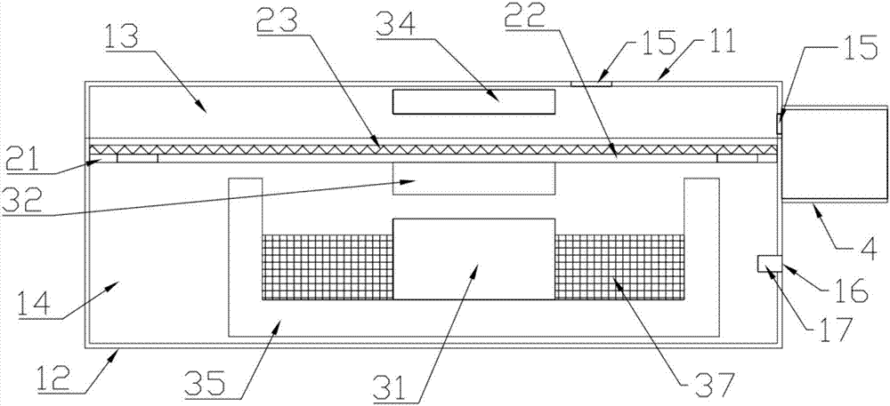
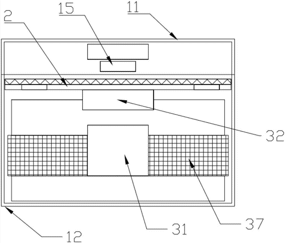
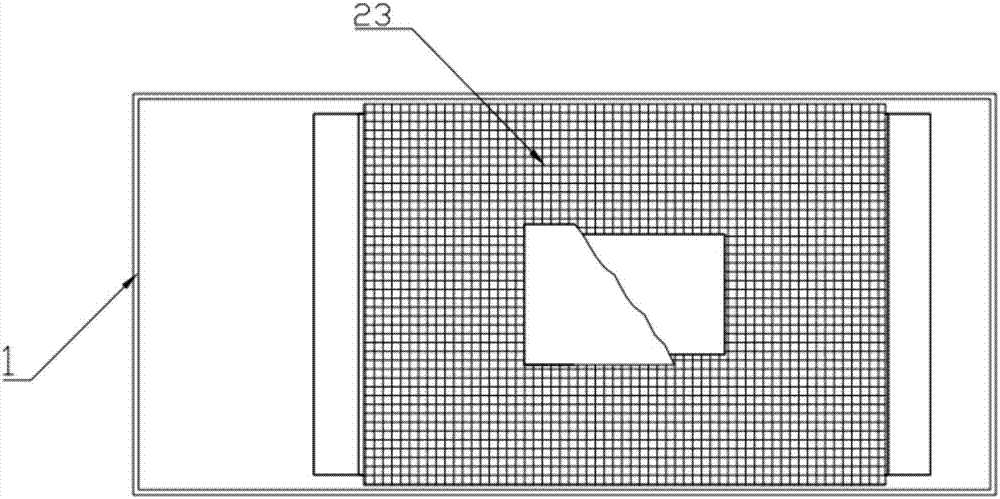
[0058] This embodiment provides a receiver, such as Figure 1 to Figure 3 As shown, it includes a casing 1 , a diaphragm mechanism 2 , an electromagnetic assembly and a soft magnet 32 ​​.

[0059] Such as figure 1 As shown, the shell 1 includes a first shell 11 made of a first bottom surface and a side wall, and a second shell 12 made of a second bottom surface and a side wall; the second shell 12 is detachably connected to the first shell The body 11 is fastened to form an inner cavity. The diaphragm mechanism 2 is arranged between the openings of the first shell 11 and the second shell 12, and divides the inner cavity of the shell 1 into a first cavity 13 close to the first bottom surface and a second cavity close to the second bottom surface Body 14. That is, the inner cavity of the first housing 11 serves as the first cavity 13 , and the inner cavity of the second housing 12 serves as the second cavity 14 . Both the first housing 11 and the second housing 12 are prefer...

Embodiment 2

[0086] This embodiment provides a receiver, such as Figure 4 As shown, the difference between it and the receiver provided in Embodiment 1 is that the soft magnet 32 ​​is replaced by the second permanent magnet 33, and the corresponding electromagnetic assembly includes a coil 37 arranged in the second cavity 14 and a coil embedded in the coil 37. The stem 36, other structures are the same as those of the receiver in Embodiment 1.

[0087] The receiver of this structure, if the polarity of the bottom one end of the second permanent magnet 33 is the S pole, the polarity of the top end is the N pole; Pass forward electricity to the coil 37, the coil 37 produces an electromagnetic field, and it is towards the second permanent magnet 33 The polarity of one end of the bottom is the S pole, according to the repulsion of the same sex, the second permanent magnet 33 is driven to drive the vibrating plate 22 to vibrate upward; The polarity of the bottom end of the second permanent ma...


PUM


Abstract

The invention discloses a receiver and its assembly process. The receiver includes a shell, a diaphragm mechanism, a first magnet and an electromagnetic assembly arranged in the shell. The first magnet is fixed on the surface of the vibrating plate facing the second cavity; the fixed frame of the diaphragm mechanism is directly fixed on the casing, and the electromagnetic assembly is arranged in the inner cavity of the casing to drive the first magnet to drive the vibrating plate Electromagnetic driving force for reciprocating vibration. In the receiver of this structure, the shell is arranged as two shells, and the fixing frame of the diaphragm mechanism is directly installed on the shell, so that the components in the receiver are reduced, and the structure and installation process of the receiver are simplified. The assembly process is: the electromagnetic components are pre-fixed on the second housing to form the first module; the first magnet and the diaphragm mechanism are pre-fixed to form the second module; the first housing forms the third module, and finally the three modules are assembled Together, the assembly process of the receiver can be completed, a modular installation process can be realized, and the assembly efficiency of the receiver can be improved.

Description

technical field [0001] The invention relates to the technical field of acoustic components, in particular to a receiver and an assembly process. Background technique [0002] The receiver is an electroacoustic device that converts audio electrical signals into audio signals without sound leakage. It is widely used in communication terminal equipment such as mobile phones, fixed phones, and earphones to realize audio output. [0003] With the continuous development of mobile devices, the structure of the receiver is constantly updated. For example, Japanese patent document JP10301573A discloses a receiver, which includes a cover, a bottom plate, a magnetic steel, a coil, an iron core, a diaphragm and an annular isolation cylinder. Wherein, the cover body has a bottom opening, and the bottom plate is arranged on the bottom opening of the cover body to enclose a closed installation cavity; the annular isolation cylinder is fixed on the top surface of the bottom plate, and the d...

Claims


Application Information

Patent Timeline
Patent Type & Authority Applications(China)
IPC IPC(8): H04R1/10
CPCH04R1/1058H04R2201/105
Inventor 陈晓明吴哲
Owner SUZHOU YICHUAN TECH CO LTD
Why Eureka
Try Eureka