Microphone Calibration Compensation Derived from Coupler Transfer Function

A technology of transfer function and coupler, applied in sensor, frequency response correction, medical science, etc., can solve problems such as impedance mismatch

Active Publication Date: 2021-03-02
INTERACOUSTICS
View PDF6 Cites 0 Cited by
  • Summary
  • Abstract
  • Description
  • Claims
  • Application Information

AI Technical Summary

Problems solved by technology

This makes the notch jump to about 17kHz, but the apparent error remains due to the impedance mismatch towards the notch

Method used


Image

  • Microphone Calibration Compensation Derived from Coupler Transfer Function
  • Microphone Calibration Compensation Derived from Coupler Transfer Function
  • Microphone Calibration Compensation Derived from Coupler Transfer Function

Examples


Embodiment Construction

[0072] The following detailed description is presented in conjunction with the accompanying drawings as a description of various non-limiting embodiments including methods, diagnostic tools and audiological diagnostic systems according to the present invention.

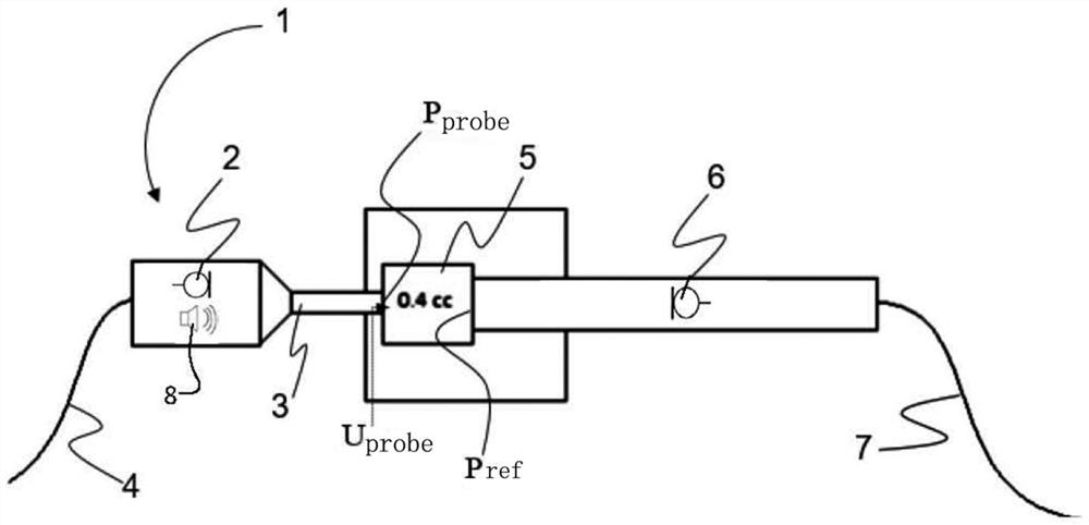
[0073] refer to figure 1, showing a schematic illustration of a microphone calibration setup applying a 0.4cc coupler, a reference microphone, and an appropriate sound source configured to generate a sound field in the coupler (since the probe includes at least a sound source and a microphone, the sound source is not shown in the figure shown in, see for example [1]). This setup constitutes a non-limiting example of a setup that can be used to implement the method according to the invention.

[0074] figure 1 A probe unit (equivalently, an acoustic unit) generally indicated by reference number 1 is shown, comprising a probe microphone 2 and a sound source 8 . Furthermore, an acoustic tube 3 is shown, which is confi...


PUM


Abstract

The present application discloses a calibration compensation of a microphone derived from a coupler transfer function, and specifically discloses a method for determining the sensitivity of a microphone in an acoustic unit, the method comprising: providing an acoustic unit; providing an acoustic coupler having at least one internal cavity, the The cavity is also in acoustic communication with a reference microphone; acoustic communication is established between the acoustic coupler and the acoustic unit, the cavity is also provided with an inlet opening; the sensitivity of the acoustic unit is determined, wherein the sensitivity is determined as acoustic The ratio between the output voltage of the unit and the reference sound pressure generated in the cavity by the sound source and measured by the reference microphone of the acoustic coupler is multiplied by a transfer function as a function of frequency, wherein the transfer function is The input impedance Z at the inlet opening of the acoustic coupler in and the transmission impedance Z between the inlet opening of the acoustic coupler and the location at which the reference sound pressure is measured by the reference microphone trans The function.

Description

technical field [0001] The present invention relates generally to determining the sensitivity of a microphone as a function of frequency, and in particular to determining the sensitivity of a microphone in an acoustic unit such as an acoustic probe for audiodiagnosis. Background technique [0002] Some modalities in audiology involve the measurement of sound pressure in the ear canal. Measuring the correct sound pressure from the outset is also the basis for estimating other relevant quantities such as the sound pressure at the eardrum, the sound intensity or the sound energy transmitted to the inner ear. [0003] A modality in audiology involving sound pressure measurement in the ear canal includes otoacoustic emissions (OAE). In OAE measurements, sounds produced by well-functioning hair cells in the cochlea that are loud enough to be recorded by a microphone positioned in the patient's (ie subject's) ear canal are measured. OAE measurements can provide information about ...

Claims


Application Information

Patent Timeline
Patent Type & Authority Patents(China)
IPC IPC(8): H04R29/00
CPCH04R29/004H04R2420/05A61B5/125A61B2560/0223A61B2560/0431H04R3/04
Inventor K·R·诺加德
Owner INTERACOUSTICS
Why Eureka
Try Eureka