
Control local area network CAN chip

A technology for controlling local area network and CAN bus, applied in the direction of bus network, data exchange network, digital transmission system, etc., can solve the problems of low reliability, high cost, slow response speed, etc.

Active Publication Date: 2017-11-24
GREE ELECTRIC APPLIANCES INC OF ZHUHAI
View PDF11 Cites 5 Cited by
  • Summary
  • Abstract
  • Description
  • Claims
  • Application Information

AI Technical Summary

Problems solved by technology

[0002] The reversing function of CAN non-polarity communication currently used is usually to build a reversing circuit outside the CAN chip, and identify the polarity and control the polarity switching through the Microcontroller (MCU) outside the CAN chip. However, this kind The circuit of the implementation scheme needs to build a commutation circuit externally. The circuit is relatively complex, prone to failure, low reliability, and needs to be equipped with an MCU, which costs a lot.
Or, there is another implementation scheme, which encapsulates the commutation circuit inside the CAN chip, but still requires an external MCU to identify the polarity and then send a switching signal to the commutation circuit. The commutation function of this technical solution still requires an external MCU to identify And control, the response speed is slow, and MCU still needs to be configured, which wastes MCU resources and costs high
[0003] Aiming at the technical problem of the high cost of CAN non-polarity communication technical solutions in related technologies, no effective solution has been proposed yet

Method used


Image

  • Control local area network CAN chip
  • Control local area network CAN chip
  • Control local area network CAN chip

Examples


Embodiment Construction

[0021] In order to enable those skilled in the art to better understand the solutions of the present invention, the following will clearly and completely describe the technical solutions in the embodiments of the present invention in conjunction with the drawings in the embodiments of the present invention. Obviously, the described embodiments are only It is an embodiment of a part of the present invention, but not all embodiments. Based on the embodiments of the present invention, all other embodiments obtained by persons of ordinary skill in the art without making creative efforts shall fall within the protection scope of the present invention.

[0022] It should be noted that the terms "first" and "second" in the description and claims of the present invention and the above drawings are used to distinguish similar objects, but not necessarily used to describe a specific sequence or sequence. It is to be understood that the data so used are interchangeable under appropriate ...


PUM


Abstract

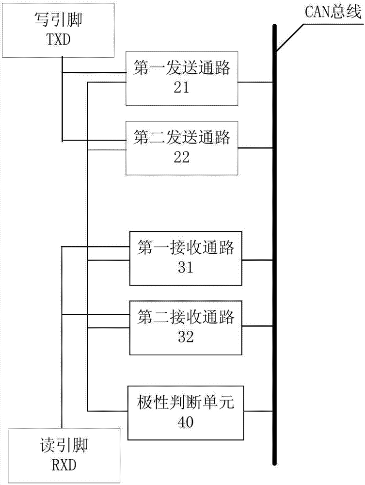
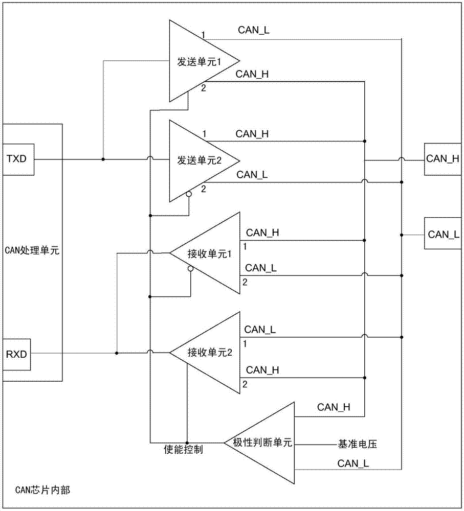
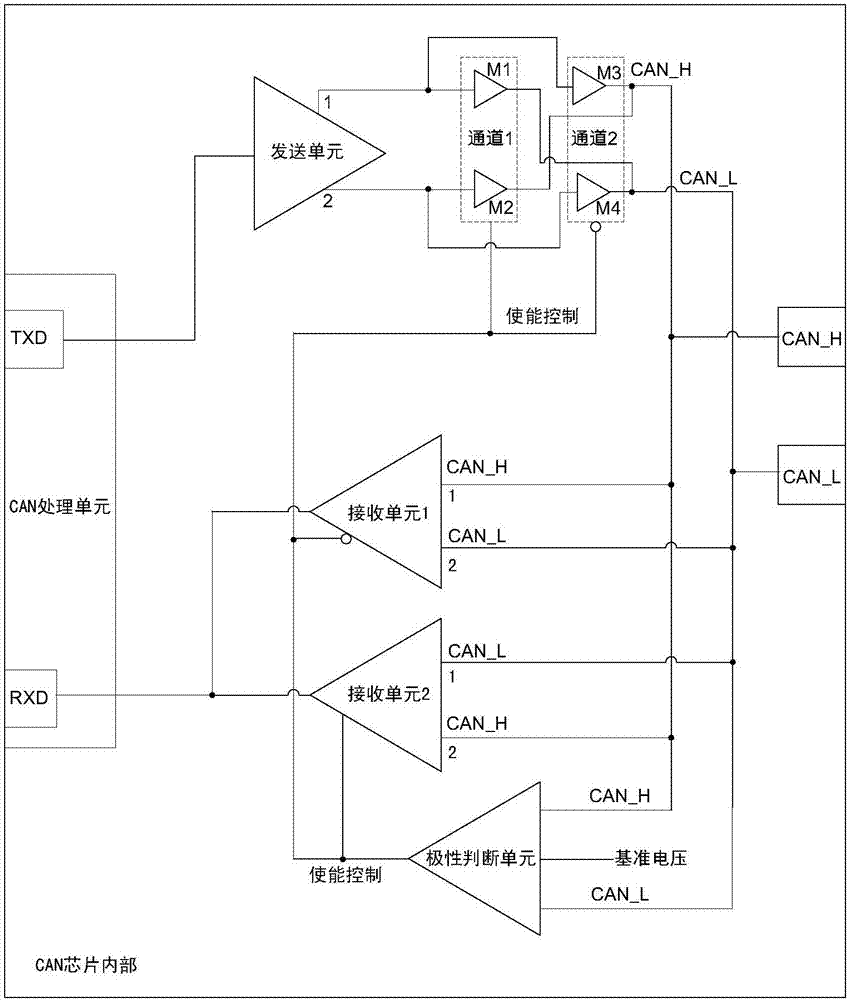
The invention discloses a control local area network CAN chip. The chip comprises two sending accesses, two receiving accesses, and a polarity judgment unit, wherein each sending access is used for converting the logic level into the differential level, the input end of each sending access is connected with a write pin TXD of the CAN chip, and the output end is connected with the CAN bus through two different modes of connection; each receiving access is used for converting the differential level into the logic level, the output end of each receiving access is connected with a read pin RXD of the CAN chip, and the input end is connected with the CAN bus through two different modes of connection; the input end of the polarity judgment unit is connected with the CAN bus and used for gating one of two sending accesses and one of two receiving accesses according to the differential level size of the CAN bus. A technical problem that the technical scheme of the CAN non-polarity communication in the related technology is high in cost is solved by using the CAN chip disclosed by the invention.

Description

technical field [0001] The invention relates to the field of non-polarity communication of a controller area network (CAN for short), in particular to a CAN chip of a control area network. Background technique [0002] The reversing function of CAN non-polarity communication currently used is usually to build a reversing circuit outside the CAN chip, and identify the polarity and control the polarity switching through the Microcontroller (MCU) outside the CAN chip. However, this kind The circuit for implementing the scheme needs to build a commutation circuit externally. The circuit is relatively complex, prone to failure, low in reliability, and needs to be equipped with an MCU, which is expensive. Or, there is another implementation scheme, which encapsulates the commutation circuit inside the CAN chip, but still requires an external MCU to identify the polarity and then send a switching signal to the commutation circuit. The commutation function of this technical solution...

Claims


Application Information

Patent Timeline
IPC IPC(8): H04L12/40
CPCH04L12/40013H04L2012/40215
Inventor 刘桂鹏玉维友唐杰贺小林李翠娟陈位旭
Owner GREE ELECTRIC APPLIANCES INC OF ZHUHAI
Learn More