
Anti-explosion balance valve applied to battery cell module

A battery cell module and balance valve technology, which is applied to battery pack parts, circuits, electrical components, etc., can solve the problems of reduced service life of key components of the battery cell, damage to electronic devices, and air pressure discharge to the outside, achieving easy installation and operation , increase the service life, and solve the effect of damage

Pending Publication Date: 2017-11-24
惠州市沃瑞科技有限公司
View PDF11 Cites 4 Cited by
  • Summary
  • Abstract
  • Description
  • Claims
  • Application Information

AI Technical Summary

Problems solved by technology

[0002] In the current development stage of new energy vehicles, the core component inside is the battery pack. There are N battery modules in the battery pack, and the battery components are inside the module. Since the battery components are safety-critical components , under working conditions, the electrolyte inside the cell will accumulate a certain amount of chemical energy over time, which will cause the internal pressure to rise. After reaching the set limit value, it will act on the explosion-proof plate on the cell shell, The internal pressure of the battery is directly connected to the inside of the battery module, but because the current battery module shell is designed as a sealed shell, the air pressure cannot be discharged from the inside of the module after the abnormal pressure limit value of the solid battery, which is easy Leading to a decrease in the service life of key components of the internal battery and damage to electronic devices

Method used


Image

  • Anti-explosion balance valve applied to battery cell module
  • Anti-explosion balance valve applied to battery cell module
  • Anti-explosion balance valve applied to battery cell module

Examples


Embodiment Construction

[0029] In order to enable those skilled in the art to better understand the technical solution of the present invention, the product of the present invention will be further described in detail below in conjunction with the embodiments and accompanying drawings.

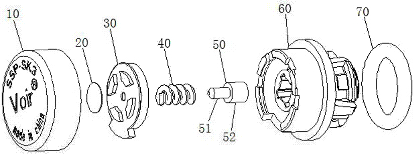
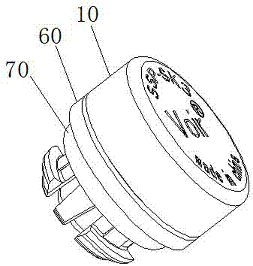
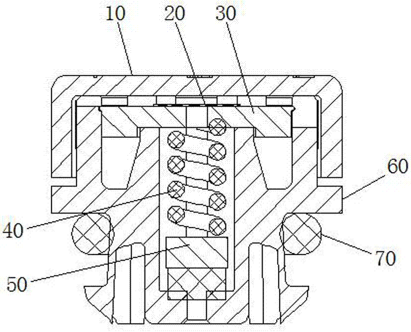
[0030] Such as Figure 1 to Figure 7 As shown, an explosion-proof balance valve applied to the battery module includes a valve main body 60 and a protective cover 10, one end of the valve main body 60 is connected to the protective cover 10, and the other end of the valve main body 60 is sleeved There is a sealing ring 70, and a breathable assembly for blocking the electrolyte is provided between the protective cover 10 and the valve body 60. The breathable assembly includes a breathable gland 30, and a breathable membrane is arranged outside the breathable gland 30 Sheet 20, the valve body 60 is provided with a first gas channel 65 through the valve body 60, the first gas channel 65 is a stepped channel, and the fir...


PUM


Abstract

The invention discloses an anti-explosion balance valve applied to a battery cell module. The anti-explosion balance valve comprises a valve body and a protection cover. One end of the valve body is connected with the protection cover. A ventilated assembly unit is arranged between the protection cover and the valve body. A sealing ring is sleeved on the other end of the valve body. The interior of the valve body is equipped with a first air channel communicated with the valve body. A flexible sealing assembly is arranged in the first air channel. One end of the flexible sealing assembly is in contact type sealing connection with one end of the first air channel. The other end of the flexible sealing assembly is in contact type connection with the ventilated assembly unit. A second air channel is arranged between the ventilated assembly unit and the protection cover. A third air channel is arranged between the protection cover and the valve body. The first air channel is communicated with the second air channel. The second air channel is communicated with the third air channel. The anti-explosion balance valve applied to the battery cell module provided by the invention has the advantages that a structure is simple, the cost is low, the operation is simple and convenient, an electrolyte permeation function in a battery cell is obstructed, and the interior of a product is ventilated with the outside world.

Description

technical field [0001] The invention relates to an explosion-proof balance valve, in particular to an explosion-proof balance valve applied to a cell module. Background technique [0002] In the current development stage of new energy vehicles, the core component inside is the battery pack. There are N battery modules in the battery pack, and the battery components are inside the module. Since the battery components are safety-critical components , under working conditions, the electrolyte inside the cell will accumulate a certain amount of chemical energy over time, which will cause the internal pressure to rise. After reaching the set limit value, it will act on the explosion-proof plate on the cell shell, The internal pressure of the battery is directly connected to the inside of the battery module, but because the current battery module shell is designed as a sealed shell, the air pressure cannot be discharged from the inside of the module after the abnormal pressure lim...

Claims


Application Information

Patent Timeline
Patent Type & Authority Applications(China)
IPC IPC(8): H01M2/12H01M50/317H01M50/333H01M50/35H01M50/383
CPCH01M50/317H01M50/383H01M50/333H01M50/35Y02E60/10
Inventor 汪水
Owner 惠州市沃瑞科技有限公司
Learn More