High-resolution imaging method for radar based on multi-beam scanning

An imaging method and multi-beam technology, applied in radio wave measurement systems, instruments, etc., can solve problems such as aliasing of imaging results, difficulty in azimuth resolution of adjacent targets, affecting imaging performance, etc., and achieve the effect of high resolution avoidance

Active Publication Date: 2017-11-24
UNIV OF ELECTRONICS SCI & TECH OF CHINA
View PDF5 Cites 13 Cited by
  • Summary
  • Abstract
  • Description
  • Claims
  • Application Information

AI Technical Summary

Problems solved by technology

Due to the Doppler symmetry and the small Doppler gradient in the forward-looking area of ​​the carrier aircraft, it is difficult to achieve high azimuth resolution of adjacent targets
In the document "Zheng S.X.LIZ.BAO.Highly Squint DBSImaging[J].Modern Radar,2004,1:008.", a Doppler beam sharpening imaging method under a large oblique angle of view is proposed, using narrow beam scanning , to achieve large-scale Doppler beam sharpening imaging in the airborne oblique forward-looking area. Although this method can improve the target azimuth resolution to a certain extent, the echo accumulation time of the narrow beam sweeping across the target point is short, and it is difficult to achieve azimuth phase resolution. For the resolution of adjacent targets, especially in the large front squint area, the rate of change of the target Doppler gradient is small, and it is more difficult to achieve the azimuth resolution of adjacent targets
In the document "Bao H R W T, Bao-chang Z L.A Novel Algorithm for StitchingDoppler Beam Sharpening Images Based on INS Information [J]. Journal of Electronics & Information Technology, 2012, 6:012.", a Doppler algorithm based on inertial navigation information is proposed. The essence of the Le beam sharpening image stitching algorithm is to use the azimuth fast Fourier transform to increase the coherent accumulation time of the echo and improve the azimuth resolution of the Doppler beam sharpening, but the use of a wide beam will cause the beam to sweep the front view In the region, due to the Doppler symmetry problem, the imaging results are aliased, which affects the imaging performance

Method used


Image

  • High-resolution imaging method for radar based on multi-beam scanning
  • High-resolution imaging method for radar based on multi-beam scanning
  • High-resolution imaging method for radar based on multi-beam scanning

Examples


Embodiment Construction

[0024] In order to facilitate those skilled in the art to understand the technical content of the present invention, the content of the present invention will be further explained below in conjunction with the accompanying drawings.

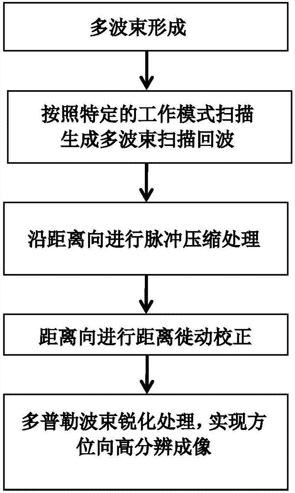
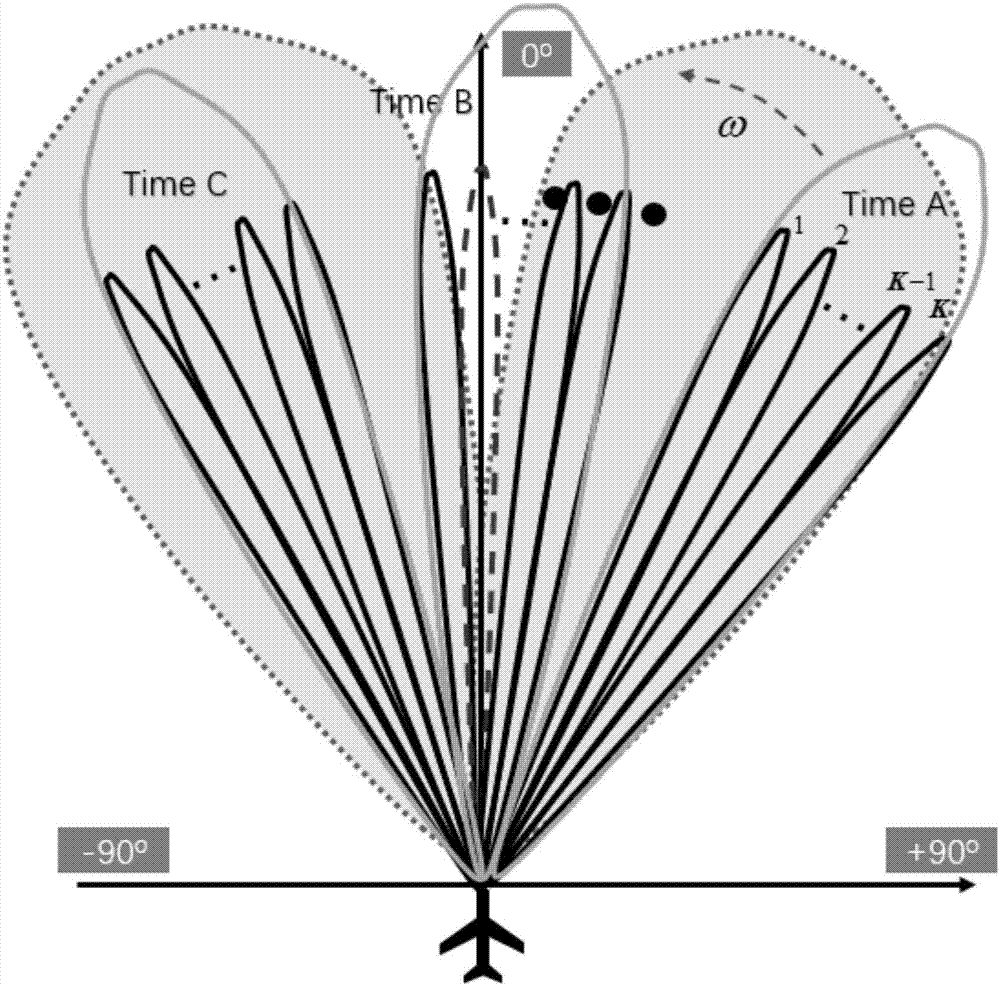
[0025] Such as figure 1 Shown is the solution flow chart of the present invention, the technical solution of the present invention is: a radar high-resolution imaging method based on multi-beam scanning, if there is a sub-beam passing through the central axis at a certain moment during scanning, then turn off the sub-beam The transceiver system corresponding to the beam; when the sub-beam passes through the central axis, the transceiver system corresponding to the sub-beam is turned on.

[0026] Specifically include the following steps:

[0027] S1. Multiple receiving antennas arranged in a linear array are used to realize multiple beams through beamforming technology;

[0028] In this embodiment, the contents of the application are described i...


PUM


Abstract

The invention discloses a high-resolution imaging method for radar based on multi-beam scanning, and is applied in the field of radar imaging. The method comprises the steps: forming a plurality of received subbeams through the digital beam forming technology, and enabling the received beams to employ a folding-fan working mode for the scanning of a front view region, thereby reducing the front view Doppler fuzzy region. Meanwhile, the bigger Doppler bandwidth is obtained through the echo overlapping of multiple beams, thereby improving the target azimuth resolution of a big front view region of an airborne platform, and achieving the large-range high-resolution imaging of the big front view region of a radar. The method proposed by the invention can be used for solving a problem of inherent conflicts between the resolution and the front view imaging blind region in the conventional Doppler beam sharpening technique.

Description

technical field [0001] The invention belongs to the field of radar detection and imaging, and in particular relates to a scanning radar forward-looking azimuth high-resolution technology. Background technique [0002] Radar uses emission and electromagnetic waves to realize functions such as target reconnaissance, surveillance, positioning, and identification. Its operating spectrum is wide. Compared with optical detection, it can work all day and all day under the influence of various adverse weather and environmental factors. . Its wide adaptability has very wide application and research value in military and civilian fields such as marine and hydrological observation, environmental and disaster monitoring, land and sea tracking and rescue. [0003] In radar imaging, the realization of radar front squint imaging is of great significance for target reconnaissance, surveillance, positioning, tracking, target recognition of friend and foe, and precise guidance. Due to the D...

Claims


Application Information

Patent Timeline
Patent Type & Authority Applications(China)
IPC IPC(8): G01S7/02
CPCG01S7/02
Inventor 张寅毛德庆徐帆云李昌林沙连童吴阳张永超黄钰林杨建宇
Owner UNIV OF ELECTRONICS SCI & TECH OF CHINA
Why Eureka
Try Eureka