Swing rod type conveying tube of large roller
A technology for conveying pipes and rollers, applied in the field of pendulum-type conveying pipes and large-scale rotating facilities, to achieve the effects of reducing manufacturing accuracy and installation accuracy, saving manufacturing costs, and ingenious design
- Summary
- Abstract
- Description
- Claims
- Application Information
AI Technical Summary
Problems solved by technology
Method used
Image

Examples
Embodiment 1
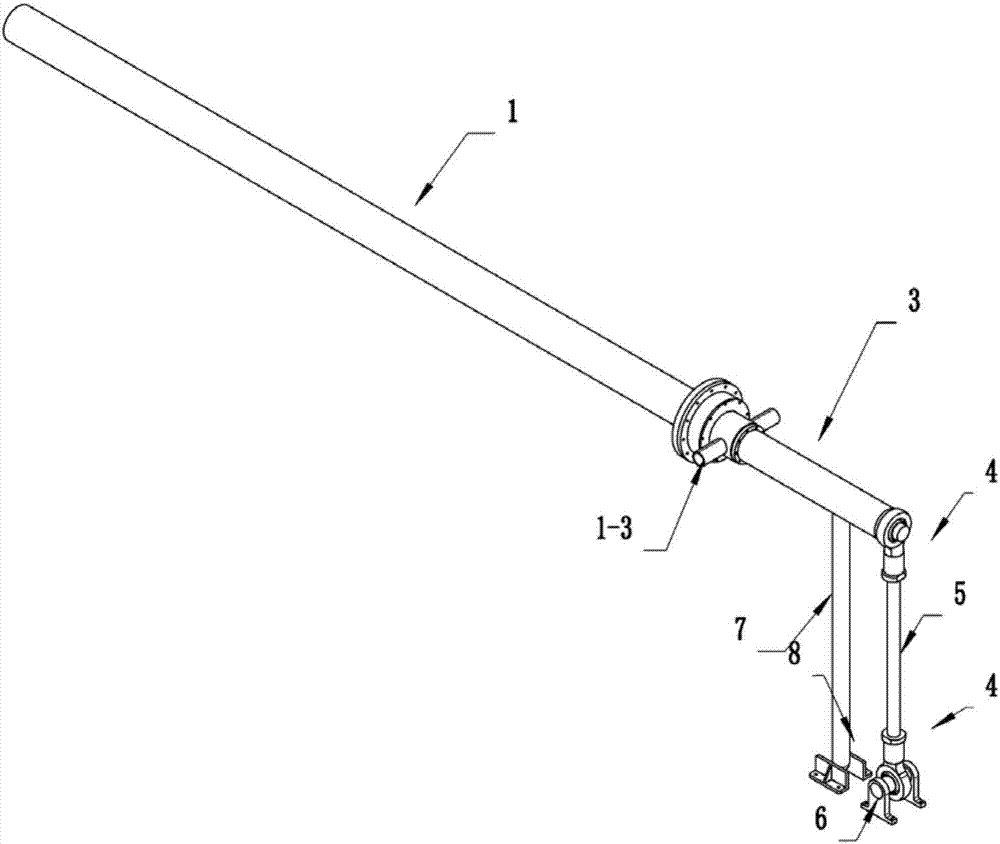
[0026] see figure 1 , Figure 11 A pendulum-type delivery pipe for a large drum includes: air delivery pipe 1, bearing 2, and balance pipe 3; the outer wall of the air delivery pipe 1 is fixed in the inner ring of the bearing 2, and the outer ring of the bearing 2 passes through the bearing seat 2 -1 is fixed in the shaft hole on the end face of the drum 9, and an air inlet pipe 1-3 is arranged on the air pipe 1 exposed outside the drum 9, and the air inlet pipe 1-3 is connected to the air source; on the surface of the air pipe 1 inside the drum 9 A lot of jet holes 1-1 are set, which can deliver fresh air, hot air and even liquid to the inside of the drum 1. A balance pipe 3 is set at the end of the air pipe 1 exposed outside the drum 9, so as to balance the air pipe 1 installed on the cantilever inside the drum 9. Weight, such setting can allow air delivery pipe 1 and cylinder 9 to do relative rotation, has realized the function of conveying gas, liquid in the rotating cyli...
Embodiment 2
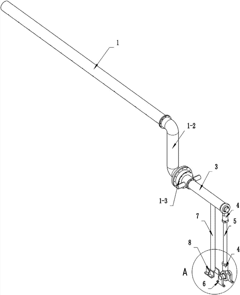
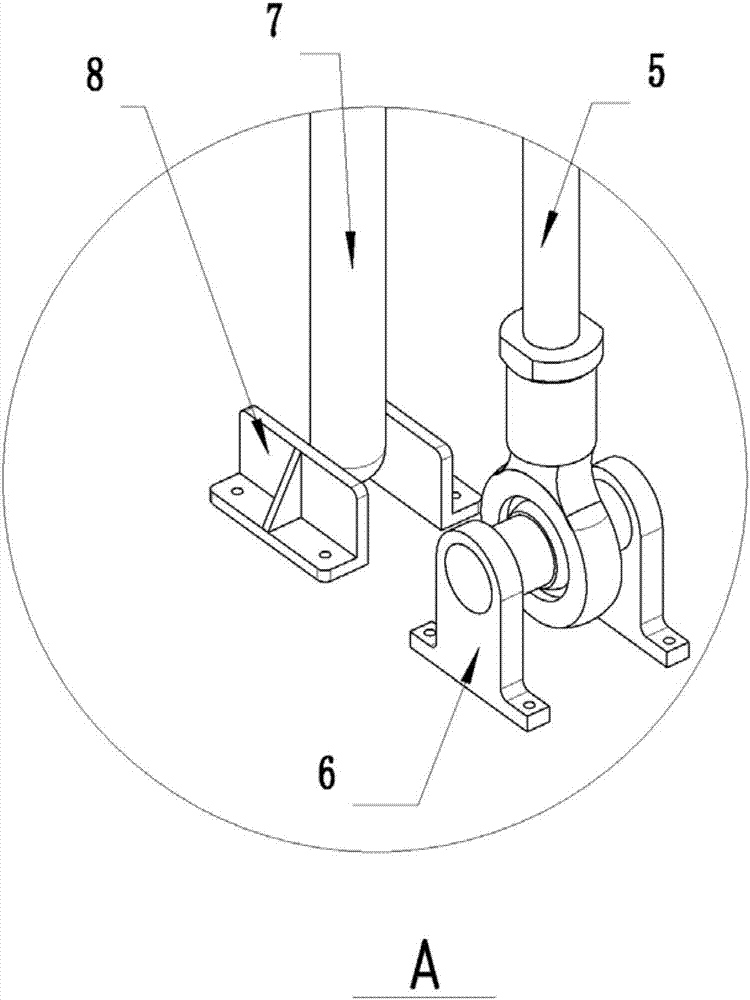
[0029] The structure of embodiment 1 can be used to transport gas and liquid in the rotating cylinder, but there are considerable limitations. When the material that needs to be stirred inside the drum 9 is higher than half of the volume, the gas delivery pipe 1 is buried in the material pile, so that The gas transmission is not smooth, and a section of Z-shaped elbow 1-2 is set on the gas transmission pipe 1, and the gas transmission pipe 1 arranged inside the drum 9 is lifted up, so that the air injection holes 1-1 on the gas transmission pipe 1 are placed in the drum. In the air layer at the top of 9, air or liquid can be easily and smoothly delivered continuously. In order to prevent the elevated air delivery pipe 1 from automatically toppling due to gravity, a swing bar is set on the balance pipe 3 outside the drum 9 7. The lower end of the fork 7 is not fixed, but the swing range is limited between two L-shaped fork seats 8, and the raised air pipe 1 can not freely swing ...
Embodiment 3
[0031] The structure in Example 2 solves the unobstructed air transmission, but some viscous materials will be brought to the highest end of the top of the cylinder by the rotating drum 9 before falling, and the falling materials will continuously hit the air pipe 1. The invention allows the zigzag elbow 1-2 not only to elevate the gas delivery pipe 1, but also to incline at an angle of 15 degrees to pass over the falling area of the falling objects, so as to prevent the mixing material brought to the top of the drum wall by the drum 9 from hitting the conveying pipe when it falls. trachea1.
[0032] The invention has ingenious design, simple structure, and low manufacturing cost. The inventor designed three embodiments according to common working conditions, allowing users to choose the most suitable technical solution according to their needs, and solved the technical problems of gas and liquid infusion to large drums .
PUM
 Abstract
Description
Claims
Application Information
 - R&D
- Intellectual Property
- Life Sciences
- Materials
- Tech Scout
- Unparalleled Data Quality
- Higher Quality Content
- 60% Fewer Hallucinations
Browse by: Latest US Patents, China's latest patents, Technical Efficacy Thesaurus, Application Domain, Technology Topic, Popular Technical Reports.
© 2025 PatSnap. All rights reserved.Legal|Privacy policy|Modern Slavery Act Transparency Statement|Sitemap|About US| Contact US: help@patsnap.com