
Brake apparatus for capstan of winch

A technology of braking device and winch, which is applied in the direction of hoisting device, braking actuator, slack adjuster, etc., can solve the problem of affecting the working sensitivity and service life of modern equipment, increasing the cost of ship production and use, and affecting the normal use performance of ships. and other problems, to achieve the effect of ensuring work efficiency, simplifying the structure and lowering the maintenance threshold.

Active Publication Date: 2017-11-24
MINGGUANG CITY LIUXIANG PUMP IND
View PDF5 Cites 3 Cited by
  • Summary
  • Abstract
  • Description
  • Claims
  • Application Information

AI Technical Summary

Problems solved by technology

The defect of the above-mentioned existing brake device is that only the second end of the brake band moves toward the first end under the drive of the transmission assembly during braking, so as to realize the tightness of the brake band, which will make the second end of the brake band The load on the end is much greater than that on the first end, which makes the brake band easily damaged due to uneven force
In addition, automatic structures such as the above-mentioned oil tanks will inevitably increase the production and use costs of ships, resulting in a further increase in the cost of small and medium-sized ships
More importantly, since ships often sail in harsh environments with high temperature and humidity, this will greatly affect the working sensitivity and service life of modern equipment, such as oil cylinders and even some relatively complex electric and oil circuit mechanisms. Damaged condition due to harsh environment
Once the above structure is damaged, the crew must have certain professional knowledge to carry out maintenance and replacement, otherwise it will even affect the normal performance of the ship

Method used


Image

  • Brake apparatus for capstan of winch
  • Brake apparatus for capstan of winch
  • Brake apparatus for capstan of winch

Examples


Embodiment Construction

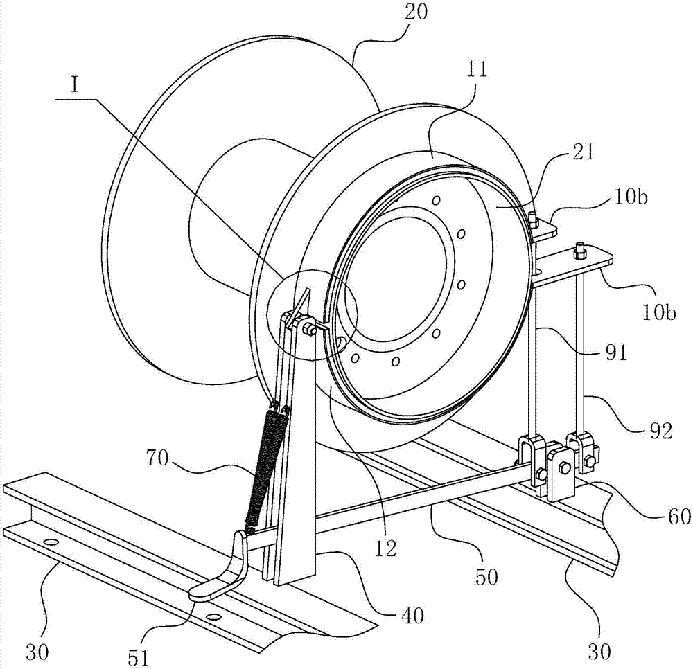
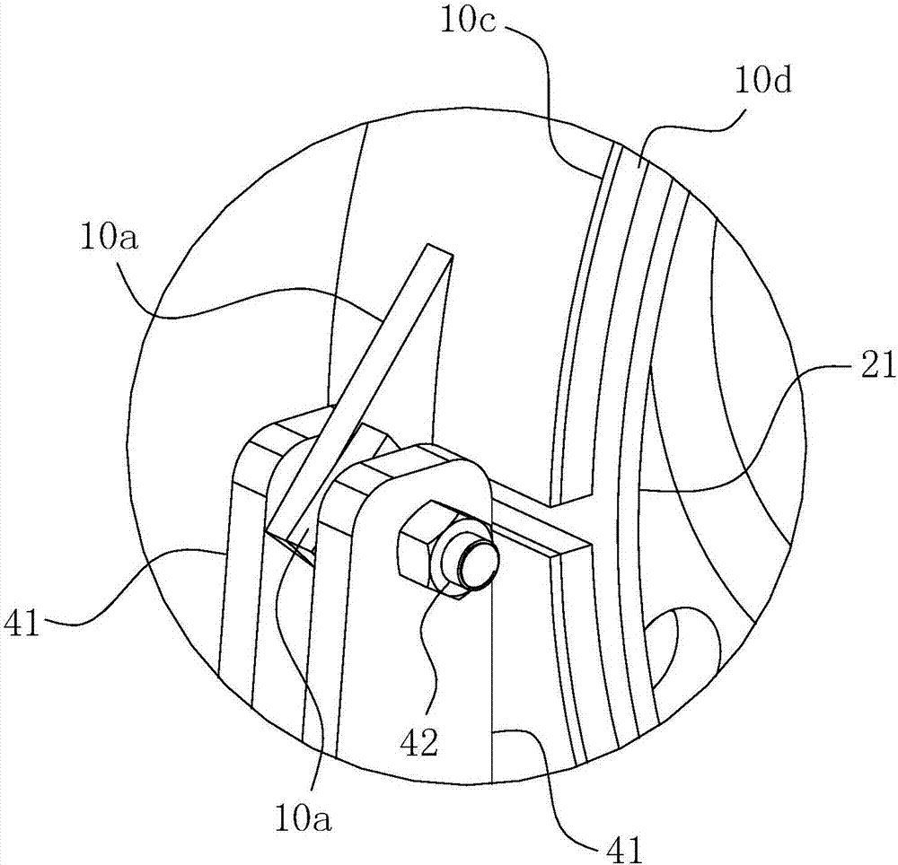
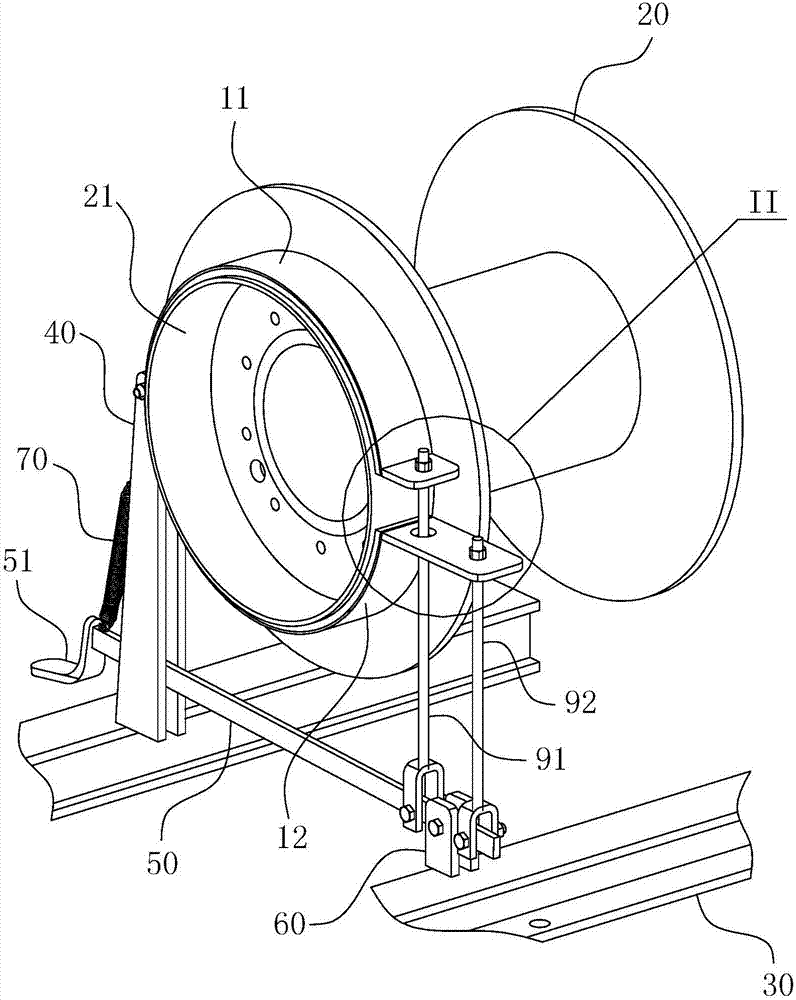
[0028] For ease of understanding, combined here Figure 1-4 , the concrete structure and working mode of the present invention are further described as follows:

[0029] The specific structure of the present invention is as Figure 1-4 As shown, its main structure includes a winch 20 with a matching ring 21 , a brake ring, a base 30 , a bracket 40 , a tension spring 70 , a pedal rod 50 , a pull rod and a hinged support 60 . During actual assembly, the brake ring is composed of two half-jointed brake arc plates, and the hinged ends at the same ends of the two brake arc plates are hinged on the bracket 40, and the other ends of the two brake arc plates are connected through the pull rod. Operated by the pedal lever 50, the opening and closing hinge action of the two brake arc plates is realized. Once the two brake arc plates produce the opening and closing action, the two brake arc plates can produce locking and loosening actions relative to the outer wall of the matching ring...


PUM


Abstract

The invention belongs to the technical field of marine winches, and particularly relates to a brake apparatus for a capstan of a winch. A brake ring of the device is formed in the mode that an upper brake arc plate and a lower brake arc plate are connected in a Hough section shape, and a matching ring is arranged at the end of the capstan in a penetrating mode; a support extends to the matching ring from a base, the adjacent ends of the two braking arc plates are coaxially hinged to the top of the support, and the axis of the hinged position is parallel to the axis of the matching ring; pull rods are arranged at the other ends relative to the hinged ends of the two braking arc plates in a penetrating mode respectively, the two pull rods are located on the same radial section of the matching ring, and the motion paths of the two pull rods avoid each other spatially; the brake apparatus further comprises a foot rest lever, a hinged support base is arranged on the base and hinged to the hinged support base, the bottoms of the two pull rods are hinged to the positions, on the two sides of the hinged support base, of a rod body of the foot rest lever respectively. The brake apparatus has the advantages of being simple in structure, low in manufacturing cost and low in operation and maintenance threshold, and the brake apparatus is extremely suitable for being used in a severe environment where a ship is located and meeting the maintenance requirements.

Description

technical field [0001] The invention belongs to the technical field of ship winches, and in particular relates to a winch brake device. Background technique [0002] At present, ships, especially large ocean-going ships, are equipped with various devices on the deck or in the hull, among which there are winches for retracting and unwinding cables. During actual operation, the winch of the winch needs to be stopped by a brake device, so as to realize the controllable retractable function of cables of any length. The current braking device for the winch winch usually includes a brake band, a transmission assembly and an oil cylinder; the first end of the brake band is fixedly installed on the deck, the second end of the brake band is hinged to the transmission assembly, and the transmission assembly is connected to the oil cylinder. When the brake device is working, the oil cylinder can drive the second end of the brake band to move to the first end through the transmission a...

Claims


Application Information

Patent Timeline
Patent Type & Authority Applications(China)
IPC IPC(8): F16D65/09F16D65/14F16D65/46B66D1/74
CPCF16D65/09F16D65/14F16D65/46B66D1/7463
Inventor 刘和明郑泉杨洋
Owner MINGGUANG CITY LIUXIANG PUMP IND
Learn More