Eureka AIR delivers breakthrough ideas for toughest innovation challenges, trusted by R&D personnel around the world.

Earth pressure cell embedding device and earth pressure cell embedding method adopting device

An earth pressure box and earth support technology, which is applied in the field of foundation soil survey, construction, infrastructure engineering, etc., can solve the problems of uncoordinated lateral deformation, affecting measurement results, and low installation efficiency, so as to reduce test errors, Guaranteed accuracy and reduced twisting effects

Active Publication Date: 2017-11-24
WUHAN UNIV
View PDF5 Cites 2 Cited by
  • Summary
  • Abstract
  • Description
  • Claims
  • Application Information

AI Technical Summary

Problems solved by technology

[0004] In actual engineering, the following problems exist in the burial of earth pressure cells by the drilling method: (1) The earth pressure cells need to be welded on thin-walled steel channels or steel cages at the construction site, the installation efficiency is low, and the earth pressure cells are easily damaged during the welding process. This leads to a decrease in the survival rate of the measuring point; (2) The earth pressure cell and the thin-walled steel channel or steel cage are buried in the soil together, and the rigidity of the thin-walled steel channel and steel cage is relatively large compared with the soil, and the soil has stress concentration and lateral deformation Inconsistency and other problems have a certain impact on the accuracy of the earth pressure measurement results; (3) the backfill fine sand is not fully consolidated, and the "loose" fine sand cannot effectively transmit the earth pressure to the earth pressure cell, resulting in the measurement results of the earth pressure cell Distortion; (4) Thin-walled steel channels or steel cages are long, which is prone to "torsion", making the axis direction of the earth pressure cell not parallel to the direction to be measured, which affects the measurement results; (5) Thin-walled steel channels or steel cages cannot be recycled after being buried in the soil , the embedding method is not economical

Method used


Image

  • Earth pressure cell embedding device and earth pressure cell embedding method adopting device
  • Earth pressure cell embedding device and earth pressure cell embedding method adopting device
  • Earth pressure cell embedding device and earth pressure cell embedding method adopting device

Examples


Embodiment approach 1

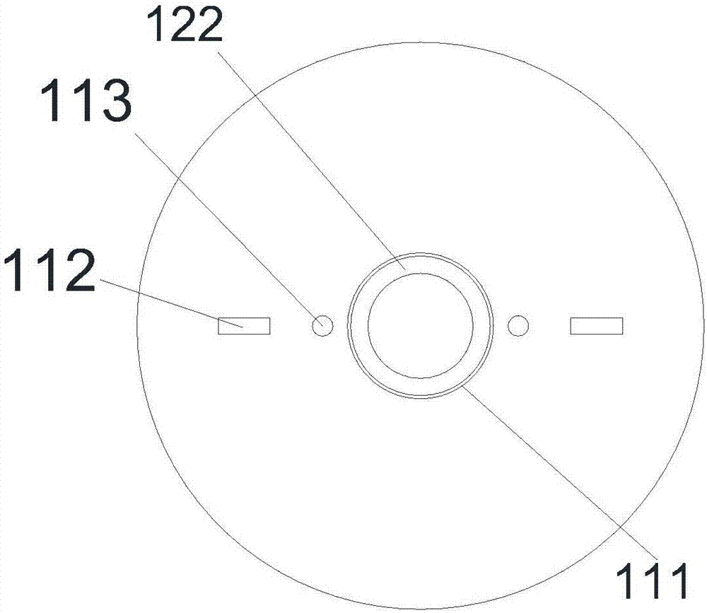
[0054] Such as figure 1 As shown, an earth pressure cell embedding device includes an embedding cylinder, an embedding rod assembly and a hoisting rope 300, figure 2 is a schematic top view of the buried barrel of this embodiment, wherein:

[0055] Described embedding tube comprises soil-putting tube 110, bulldozing mechanism and earth-supporting mechanism 130, and the lower end of described putting soil tube 110 is open, and the center of the top wall of putting soil tube 110 offers top wall through-hole 111, and puts soil tube 110 The outside of the top wall is provided with a lifting portion and the top wall is provided with an upper wire through hole 113. The bulldozer mechanism includes a bulldozer plate 121 and a bulldozer rod 122 vertically arranged at the center of the bulldozer plate 121. The bulldozer mechanism is nested in the In the described soil-setting cylinder 110, a bulldozer plate 121 is fitted with a gap between the described soil-setting cylinder 110, and...

Embodiment 2

[0081] Such as Figure 4 As shown, an earth pressure cell embedding device includes an embedding cylinder, an embedding rod assembly and a hoisting rope 300, wherein:

[0082] Such as Figure 5 , the embedding tube includes a soil tube 110, a bulldozing mechanism and a soil support mechanism 130, the lower end of the soil tube 110 is open, and the top wall center of the soil tube 110 is provided with a top wall through hole 111, and the soil tube 110 The outside of the top wall is provided with a lifting portion and the top wall is provided with an upper wire through hole 113. The bulldozer mechanism includes a bulldozer plate 121 and a bulldozer rod 122 vertically arranged at the center of the bulldozer plate 121. The bulldozer mechanism is nested In the soil-setting cylinder 110, a bulldozing plate 121 is fitted with a gap between the soil-setting cylinder 110, and the bulldozing plate 121 is provided with a lower wire through hole 123 corresponding to the upper wire throug...


PUM


Abstract

The invention provides an earth pressure cell embedding device and an earth pressure cell embedding method adopting the device. The device comprises an embedded cylinder, an embedded rod assembly and a lifting rope. The embedded cylinder comprises an earth placing cylinder, a bulldozing mechanism and an earth supporting mechanism, the lower end of the earth placing cylinder is provided with an opening, a top wall through hole is formed in the center of the top wall of the earth placing cylinder, a lifting part is arranged on the outer side of the top wall of the earth placing cylinder, and a guide wire through hole is formed in the top wall of the earth placing cylinder; the bulldozing mechanism comprises a bulldozing plate and a bulldozing rod vertically arranged in the center of the bulldozing plate; the bulldozing mechanism is nested in the earth placing cylinder, the bulldozing plate is in clearance fit with the earth placing cylinder, and a lower guide wire through hole corresponding to the upper guide wire through hole is formed in the bulldozing plate; the bulldozing rod penetrates through and is in clearance fit with the top wall through hole, and the earth supporting mechanism is stuck at the opening edge of the lower end of the earth placing cylinder; and the embedded rod assembly is composed of a plurality of connecting rods capable of detachably fixing and connecting in series, the lower end of the embedded rod assembly is detachably and fixedly connected with the bulldozing rod, and the lower end of the lifting rope is connected with the lifting part. The earth pressure cell embedding device is ingenious in design; According to the earth pressure cell embedding method adopting the device, distortion of test results is avoided, and materials are saved.

Description

technical field [0001] The invention belongs to the technical field of geotechnical engineering, and in particular relates to an earth pressure cell embedding device and an earth pressure cell embedding method using the device. Background technique [0002] The earth pressure cell is a common device used to measure earth pressure, and it is widely used in engineering fields such as roadbeds, slopes, dams, tunnels, and foundation pits. The earth pressure box can be used for long-term monitoring of the soil pressure inside or around the structure, and real-time acquisition of soil pressure change data inside or around the structure, so as to evaluate and predict the stability and safety of the structure. [0003] In actual engineering, it is necessary to bury the earth pressure cell inside the structure or in the surrounding soil to measure the earth pressure value at the corresponding position. Commonly used earth pressure cell embedding methods are: hanging cloth method, ej...

Claims


Application Information

Patent Timeline
Patent Type & Authority Applications(China)
IPC IPC(8): E02D1/00
CPCE02D1/00
Inventor 傅旭东杨之俊吕布方晴潘兵奇段毅黄斌梅灿张本蛟张雨廷徐士高贺云贾耀民
Owner WUHAN UNIV
Why Eureka
Eureka Blog
Learn More