Eureka AIR delivers breakthrough ideas for toughest innovation challenges, trusted by R&D personnel around the world.

Turnover device for packaging line

A packaging line and flipping device technology, applied in the field of packaging, can solve the problems of large footprint of the assembly line and limit the scope of application of the assembly line, so as to save the floor area, change the direction of product placement, and ensure the integrity of the effect

Inactive Publication Date: 2017-11-24
TIANJIN COTEKE AUTOMATION EQUIP CO LTD
View PDF5 Cites 2 Cited by
  • Summary
  • Abstract
  • Description
  • Claims
  • Application Information

AI Technical Summary

Problems solved by technology

[0002] The packaging line is a kind of equipment used for packaging products, but the structure of the current assembly line is simple, and the transmission structure on the assembly line can only be transmitted in a straight line, resulting in a large area of ​​the assembly line. When the assembly line cannot be used in a small space, the assembly line is limited. scope of application

Method used


Image

  • Turnover device for packaging line
  • Turnover device for packaging line
  • Turnover device for packaging line

Examples


Embodiment 1

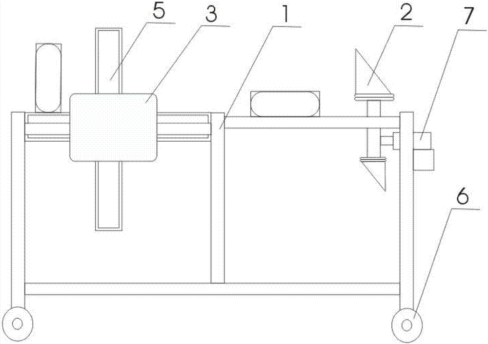
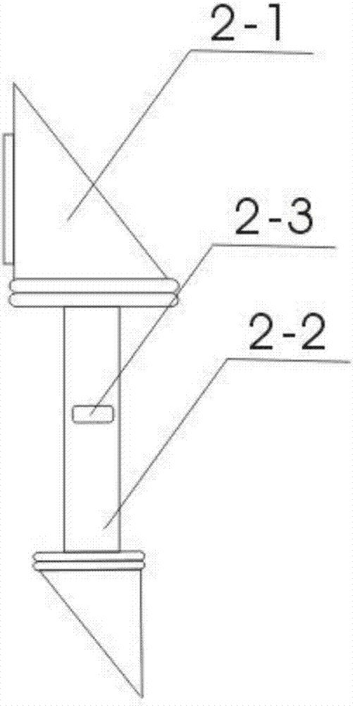
[0015] The present invention provides an overturning device 8 for a packaging assembly line 9, which includes a support 1, a material pushing structure 2, a motor 3, a rotating shaft 4, an overturning structure 5, a moving wheel 6, and a cylinder 7. A moving wheel 6 is installed on the lower side of the support 1, and the support 1. The motor 3 and the cylinder 7 are installed on the side. The output shaft of the motor 3 is connected to the shaft 4. One side of the shaft 4 is connected to the output shaft of the motor 3. The other side of the shaft 4 is connected to the bracket 1. The shaft 4 is a rotating structure. The upper side of the shaft 4 An overturning structure 5 is installed, and the overturning structure 5 is located on one side of the upper part of the bracket 1, and the other side of the upper part of the bracket 1 is equipped with a pushing structure 2, which is connected with the cylinder 7, and the pushing structure 2 is installed on the moving track, and the mo...

Embodiment 2

[0017] During use, the present invention is installed between two conveying devices, is used for changing the product conveying direction, and product is transferred to the support 1 of the present invention by conveyer belt, when product is conveyed before the pushing structure 2 on support 1 of the present invention , the sensing device on the pusher structure 2 receives the information and sends it to the controller, the controller sends the information to the cylinder 7, the cylinder 7 moves and drives the pusher structure 2 to move, and the pusher structure 2 pushes the product to the turning point On the structure 5, the induction device on the turning structure 5 receives the signal, and transmits the signal to the controller, and the controller transmits the information to the motor 3, and the motor 3 moves and drives the turning structure 5 to rotate, and the turning structure 5 drives the product and It rotates to change the direction of the product. After the rotatio...


PUM


Abstract

The invention provides a turnover device for a packaging line. The turnover device comprises a support, a pushing mechanism, a motor, a rotating shaft, a turnover structure, a movable wheel and an air cylinder, wherein the movable wheel is arranged at the lower side of the support; the motor and the air cylinder are arranged on the side surface of the support; the output shaft of the motor is connected to the rotating shaft; and one side of the rotating shaft is connected to the output shaft of the motor. The turnover device has the beneficial effects that the turnover device is one of turnover equipment and is mainly applied to the packaging line; when the turnover device is in use, the conveying direction of products can be mechanically changed, thereby shortening the length of the packaging line; the turnover device is connected to a conveyor belt for use during use, so that the conveying direction of products can be mechanically changed, thereby saving the area occupied by the packaging line and expanding the application range of the packaging line.

Description

technical field [0001] The invention relates to the packaging field, in particular to an overturning device for a packaging assembly line. Background technique [0002] The packaging line is a kind of equipment used for packaging products, but the structure of the current assembly line is simple, and the transmission structure on the assembly line can only be transmitted in a straight line, resulting in a large area of ​​the assembly line. When the assembly line cannot be used in a small space, the assembly line is limited. scope of application. Contents of the invention [0003] According to the above technical problems, the present invention provides a turning device for a packaging line, which is characterized in that it includes a bracket, a material pushing structure, a motor, a rotating shaft, a turning structure, a moving wheel, and a cylinder, and a moving wheel is installed on the lower side of the bracket. A motor and a cylinder are installed on the side of the ...

Claims


Application Information

Patent Timeline
IPC IPC(8): B65G47/52B65G47/82
CPCB65G47/52B65G47/82
Inventor 熊炎亮
Owner TIANJIN COTEKE AUTOMATION EQUIP CO LTD
Why Eureka
Eureka Blog
Learn More