Film coating mechanism for yarn balls
A technology of coating and yarn balls, which is applied in packaging, wrapping objects, transportation packaging, etc., can solve the problems that the coating can not fit well and the coating is uneven, so as to achieve convenient sealing and guarantee Coating quality, the effect of preventing excessive film feeding
- Summary
- Abstract
- Description
- Claims
- Application Information
AI Technical Summary
Problems solved by technology
Method used
Image
Examples
Embodiment 1
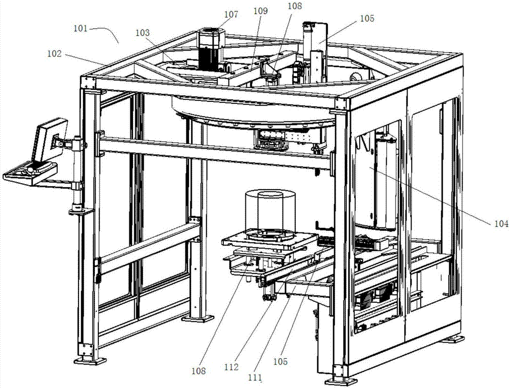
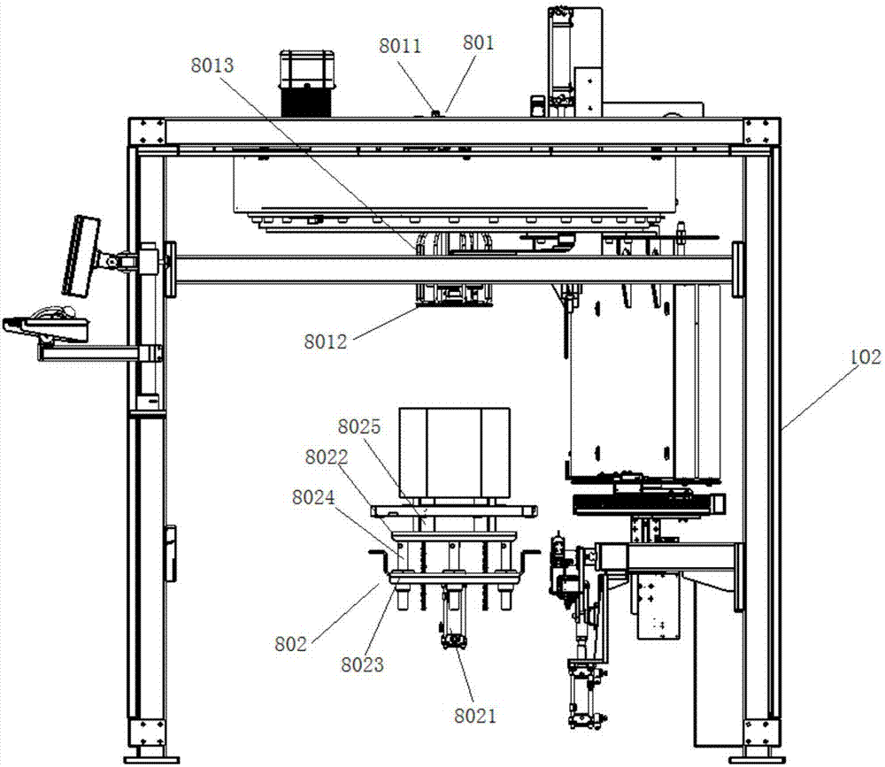
[0040] Such as figure 1 with figure 2 As shown, in order to fix the yarn clusters, this embodiment, preferably, further includes a yarn fixing assembly 108, a top beam 109 is arranged on the upper surface of the installation plate, and the yarn fixing assembly 108 includes a yarn fixing assembly 802 And the yarn pressing assembly 801, the yarn pressing assembly 802 is arranged on one side of the top beam 109, and the yarn pressing assembly 801 and the yarn pressing assembly 802 are arranged at the bottom of the coating support 102 correspondingly.
[0041] Further, in this embodiment, the yarn pressing assembly 801 includes a yarn pressing cylinder 8011 and a yarn pressing plate 8012 connected to the yarn pressing cylinder 8011, and a plurality of membrane support rods are arranged around the yarn pressing plate 8012 8013, used to support the coating wound outside the yarn cluster; the top film assembly 802 includes a top yarn cylinder 8021, a top yarn support board assembly...
Embodiment 2
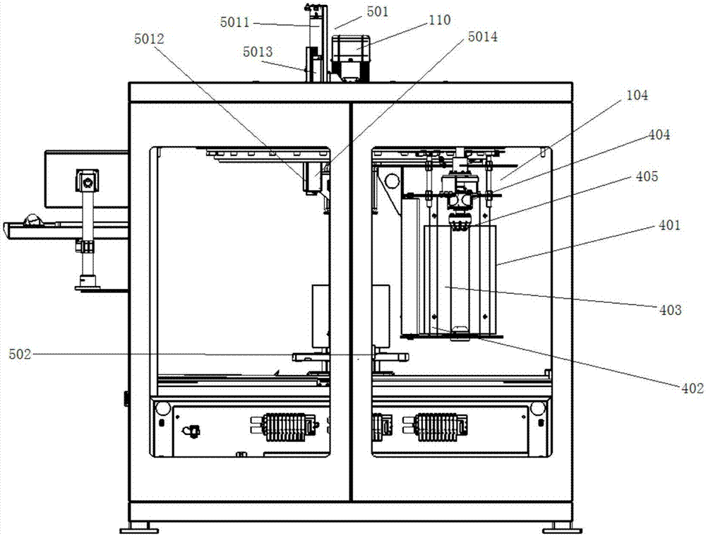
[0044] Such as figure 1 , image 3 , Figure 8 with Figure 9 As shown, in order to make the film feeding assembly 105 synchronized and more flexible. In this embodiment, preferably, the upper clamping membrane assembly 501 includes an L-shaped upper clamping membrane support 5011 and an upper claw clip 5012, and the upper clamping clamp 5012 is arranged at the bottom of the upper clamping membrane bracket 5011 A cylinder 110 for driving the upper clamp 5012 to move longitudinally and a servo motor 5013 for driving the upper clamp 5012 to move horizontally are arranged on the upper clamp 5011 .
[0045] Furthermore, in order to enable the upper claw clip 5012 to grasp the film, in this embodiment, preferably, the upper clip 5012 includes two symmetrically arranged upper grippers 5014, and the two upper grippers 5014 The closing and opening movement is driven by the air cylinder 110, which is used to clamp the film and loosen the film.
[0046] Further, in order to make th...
Embodiment 3
[0049] Such as figure 1 , Image 6 with Figure 7 As shown, in order to avoid the influence of inertia on the film winding assembly 104 when the rotating motor 107 stops rotating, in this embodiment, preferably, the film winding assembly 104 includes a film winding support 401, which is arranged on the winding A plurality of guide rollers 402 on the edge of the film support 401, and a film covering roller 403 arranged in the middle of the film winding support 401, the top of the film covering roller 403 is provided with a damping part 404, and the damping part The bottom of 404 is connected with a pressure film cone head 405 , and the damping part 404 includes a magnetic damper 406 and an angular contact ball bearing 407 connected under the magnetic damper 406 .
[0050] Further, in order to facilitate the lamination roll on the fixed lamination roller 403 , in this embodiment, preferably, an upper handle 408 and a lower handle 409 are sequentially provided on the upper part...
PUM
 Abstract
Description
Claims
Application Information
 - R&D
- Intellectual Property
- Life Sciences
- Materials
- Tech Scout
- Unparalleled Data Quality
- Higher Quality Content
- 60% Fewer Hallucinations
Browse by: Latest US Patents, China's latest patents, Technical Efficacy Thesaurus, Application Domain, Technology Topic, Popular Technical Reports.
© 2025 PatSnap. All rights reserved.Legal|Privacy policy|Modern Slavery Act Transparency Statement|Sitemap|About US| Contact US: help@patsnap.com


