Rotary pressing and positioning device for automotive mould

A technology for automotive molds and positioning devices, which is applied in the direction of positioning devices, feeding devices, storage devices, etc., can solve the problems of poor pressing effect, difficulty in controlling material sliding, and material sliding, etc. good pressure effect

Active Publication Date: 2017-11-24
CHONGQING DAJIANG ZHIXIN DIE & MOLD IND
View PDF6 Cites 3 Cited by
  • Summary
  • Abstract
  • Description
  • Claims
  • Application Information

AI Technical Summary

Problems solved by technology

[0002] At present, when designing automotive stamping dies, drawing dies generally use material guide frames to achieve sheet positioning. The positioning effect of the positive frame is often not good. In order to strengthen the positioning effect, the method of increasing the positioning height is adopted. This method has a certain effect on improving the stability of the positioning of the plate with a large surface drop. During the pressing process of the edge ring, the sheet is in a non-positioning state. The irregular sliding of the sheet caused by the gravity of the sheet itself and the instability of the external force is inevitable. It is difficult to control the sliding of the sheet while positioning the pressing. Affect the drawing quality of the plate
[0003] At present, the rotary pressing positioning device for automobile molds on the market has simple structure, high cost, and poor positioning effect, and the traditional pressing method is that the cylinder is connected to one end of the lower side of the pressing die base, and the other end is passed through The rotating device stamps the object, such as the patent number CN201020283324.8, which adopts such a stamping mode. This stamping method has a small pressure and a relatively poor pressing effect, which cannot meet people's needs. In order to solve the above-mentioned problems , the invention provides a multi-treatment sewage treatment device

Method used


Image

  • Rotary pressing and positioning device for automotive mould
  • Rotary pressing and positioning device for automotive mould
  • Rotary pressing and positioning device for automotive mould

Examples


Embodiment Construction

[0027] The technical solutions in the embodiments of the present invention will be clearly and completely described below with reference to the accompanying drawings in the embodiments of the present invention. Obviously, the described embodiments are only a part of the embodiments of the present invention, but not all of the embodiments. Based on the embodiments of the present invention, all other embodiments obtained by those of ordinary skill in the art without creative efforts shall fall within the protection scope of the present invention.

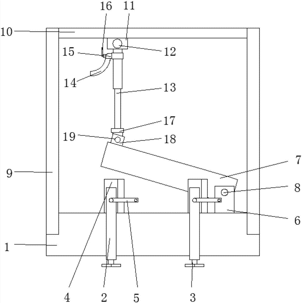
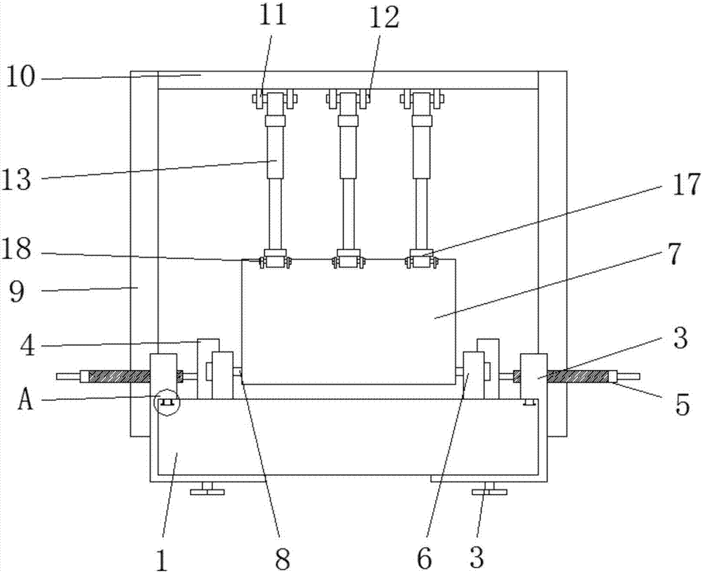
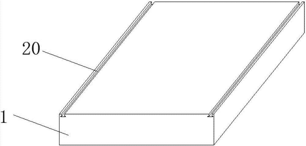
[0028] see Figure 1-6 , The present invention provides a technical solution: a rotary pressing material positioning device for an automobile mold, comprising a lower mold base 1, a fixed angle 4 and an upper mold base 7, and both ends of the top of the lower mold base 1 are provided with chute 20, and Two chutes 20 are arranged in parallel, and movable seats 2 are installed on both sides of the lower die base 1, four movable seats 2 ...


PUM


Abstract

The invention provides a rotary pressing and positioning device for an automotive mould. The device comprises a lower mould seat, fixing angles and an upper mould seat, two ends of the top of the lower mould seat are provided with two parallel slide grooves, moving seats are mounted on two sides of the lower mould seat respectively, and sliders are mounted at bottom ends of upper portions of the moving seats and arranged in the slide grooves respectively. The upper portion of each moving seat is horizontally provided with a first screw hole, the bottom of each moving seat is vertically provided with a second screw hole, a fixing screw is in threaded connection in each second screw hole, the bottom of each moving seat is connected with the bottom of the lower mould seat through the corresponding fixing screw, a rotating device is in threaded connection in each first screw hole, and the fixing angles are arranged on inner sides of the moving seats respectively. By changing of a traditional mode that an air cylinder is arranged on the lower side of a pressing mould seat and connected with one end of the pressing mould seat while the other end of the pressing mould seat performs stamping on articles through a rotating device, a pressure is directly applied to the upper mould seat from a position above the upper mould seat.

Description

technical field [0001] The invention belongs to the technical field of automobile molds, and particularly relates to a rotary pressing material positioning device for automobile molds. Background technique [0002] At present, when designing automobile stamping dies, drawing dies are generally realized by material guide frames in sheet metal positioning. The positioning effect of the main frame is often not good. In order to strengthen the positioning effect, the method of increasing the positioning height is adopted. This method has a certain effect on improving the positioning stability of the plate with a large profile drop. During the process of pressing the edge ring to death, the sheet material is in a non-positioning state, and the irregular sliding of the sheet caused by the instability of the sheet's own gravity and the external force is inevitable. It is difficult to control the sliding of the sheet while positioning and pressing the material. Affect the drawing q...

Claims


Application Information

Patent Timeline
Patent Type & Authority Applications(China)
IPC IPC(8): B21D37/10B21D43/00B21D22/22
CPCB21D22/22B21D37/10B21D43/003
Inventor 韩丽娟
Owner CHONGQING DAJIANG ZHIXIN DIE & MOLD IND
Why Eureka
Try Eureka