Rapid deployment type power transmission line deicer
A technology for transmission lines and transmission lines, which is used in cable installation, overhead installation, electrical components, etc., can solve problems such as short circuit, insulator string inclination, rapid rise or jump up and down, to avoid damage and simple device structure. Effect
- Summary
- Abstract
- Description
- Claims
- Application Information
AI Technical Summary
Problems solved by technology
Method used
Image
Examples
specific Embodiment 1
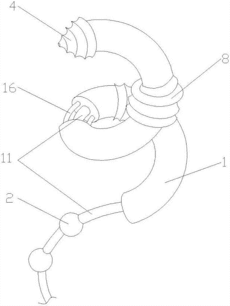
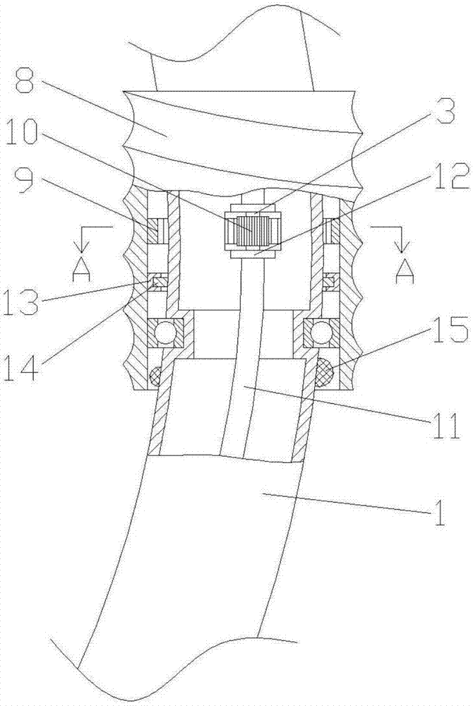
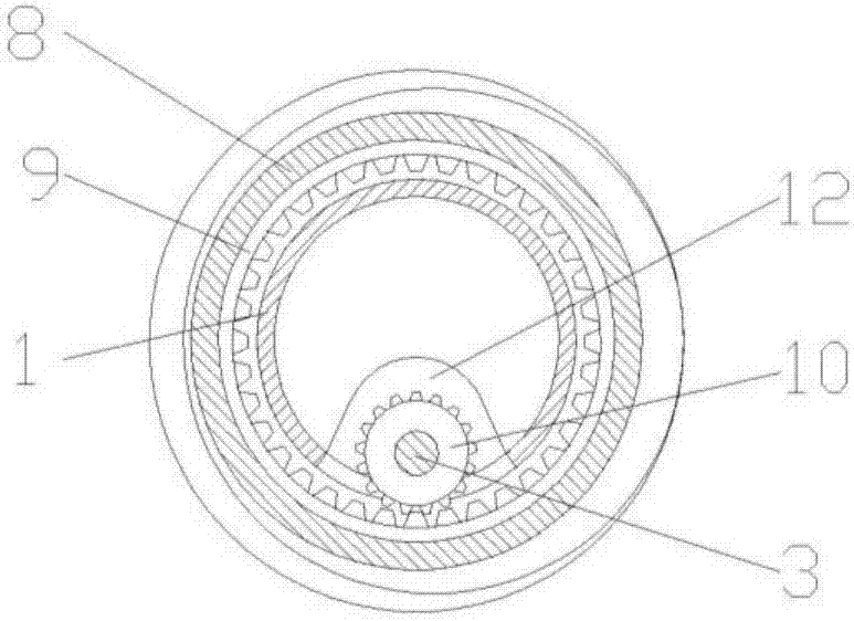
[0028] Specific embodiment 1, such as Figure 1 to Figure 4 As shown, the present invention is a rapidly deployable power transmission line deicing device, which is used to remove the ice layer around the power transmission line. It is in a spiral shape, and the head of the device body 1 is also provided with a drill bit 4, and the device body 1 has the degree of freedom to rotate around the axis of the transmission line by means of the drill bit 4 and the driving mechanism. The present invention is driven by the transmission shaft 3 during work, and the section of the ice layer is cleaned out by personnel on the ice-coated transmission line before use, and then the deicing device of the present invention is wound and arranged on the cleaned-up transmission line, and the drill bit is used to remove the ice. Holes are drilled in the ice-covered layer, and the device is continuously pushed forward by means of a driving mechanism, such as Figure 7 As shown, due to the helical s...
specific Embodiment 2
[0030] Specific embodiment 2, described drill bit comprises the drill bit 4 that is the conical structure that is connected with transmission shaft 3, is arranged on the connection structure between drill bit 4 and device body 1, and drill bit 4 has around device body 1 by means of this connection structure. The degree of freedom of axis rotation, the connection structure includes a locking ring 5 fixed to the bottom of the drill bit 4, a positioning ring 6 is clamped between the locking ring 5 and the bottom surface of the drill bit 4, and the positioning ring 6 is set Fixed on the outer wall of the device body 1, the positioning ring 6 forms rolling contact with the bottom surface of the drill bit 4 and the ring surface of the locking ring 5 by means of balls 7 respectively. The transmission shaft 3 drives the drill bit 4 to work. When the drill bit 4 advances with the device body 1, the rolling connection of the balls on the positioning ring 6 reduces the resistance and faci...
PUM
 Abstract
Description
Claims
Application Information
 - R&D Engineer
- R&D Manager
- IP Professional
- Industry Leading Data Capabilities
- Powerful AI technology
- Patent DNA Extraction
Browse by: Latest US Patents, China's latest patents, Technical Efficacy Thesaurus, Application Domain, Technology Topic, Popular Technical Reports.
© 2024 PatSnap. All rights reserved.Legal|Privacy policy|Modern Slavery Act Transparency Statement|Sitemap|About US| Contact US: help@patsnap.com


