
Retreat-stopping mechanism for preventing injection-moulded part from sticking to mould during core-pulling retreat

A technology of injection molded parts and sticky molds, which is applied in the field of mold core-pulling design, can solve problems such as difficulty in meeting the injection precision requirements of slender parts, deformation of injection molded parts, product deformation, etc., and achieves easy implementation and promotion, stable performance, and simple structure Effect

Pending Publication Date: 2017-11-21
HASCO VISION TECHNOLOGY CO LTD
View PDF6 Cites 2 Cited by
  • Summary
  • Abstract
  • Description
  • Claims
  • Application Information

AI Technical Summary

Problems solved by technology

However, during the core-pulling movement of traditional molds, the wrapping force generated when the core pulls away from the injection molded part is relatively large, which often causes product deformation. Especially for such slender injection molded parts, if the wrapping force is too large, the injection molded part may Severe deformation or fracture, so the traditional core-pulling structure is difficult to meet the injection precision requirements of slender shape parts
How to avoid the deformation caused by core-pulling during injection molding of slender parts and affect the product precision requirements has become a technical problem to be solved

Method used


Image

  • Retreat-stopping mechanism for preventing injection-moulded part from sticking to mould during core-pulling retreat
  • Retreat-stopping mechanism for preventing injection-moulded part from sticking to mould during core-pulling retreat
  • Retreat-stopping mechanism for preventing injection-moulded part from sticking to mould during core-pulling retreat

Examples


Embodiment Construction

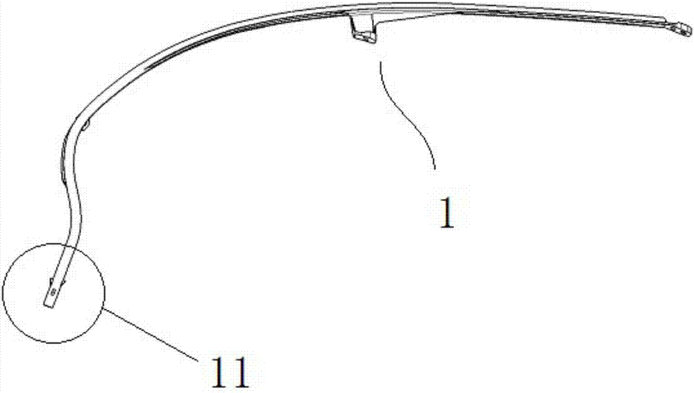
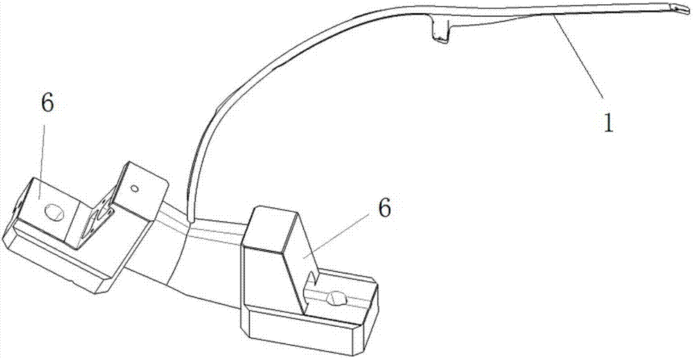
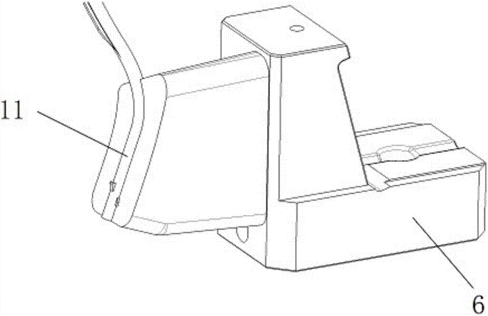
[0022] The invention discloses an anti-retraction mechanism (referred to as the anti-retraction mechanism) for preventing injection molded parts from sticking to the mold when the core is pulled back. Molds for long plastic parts. Guide the injection molded part 1 with a kind of elongated car light below (that is, a kind of injection molding product, such as figure 1 Shown) as an example to illustrate the structure and working principle of the anti-retraction mechanism. The position of the end 11 of the headlight guide injection molded part of the car has a situation of demoulding and undercutting, so a core-pulling structure needs to be provided. However, due to the slender shape of the injection molded part, simple core pulling can easily cause serious deformation of the product, resulting in distortion of the optical reflection surface and affecting the product effect. The anti-retraction mechanism of the present invention is added to the core-pulling structure, and is es...


PUM


Abstract

The invention relates to a retreat-stopping mechanism for preventing an injection-moulded part from sticking to a mould during core-pulling retreat. A core-pulling slide block and a locking block are connected in tandem along an inclined slope with a higher front part and a lower back part in a sliding manner; a core rod and a pressing plate are horizontally mounted inside the core-pulling slide block; the core rod adopts a stepped shaft, and sequentially comprises a push rod part, a shoulder part and a retreat-stopping part from the front side to the back side; the radial size of the shoulder part is the largest; the retreat-stopping part runs through the pressing plate and is in sliding fit with the pressing plate horizontally; the front surface of the locking block comprises an upper inclined plane and a lower vertical plane; the vertical plane is concave in the inclined plane; in a mould-closed state, the core rod is supported between the core-pulling slide block and the locking block through a pressure spring; the back end surface of the pressing plate is in contact with the upper part of the front surface of the locking block; the vertical back end surface of the retreat-stopping part is in contact with the lower part of the front surface of the locking block. The retreat-stopping mechanism solves the technical problem that the deformation amount of a core-pulling position of the elongated injection-moulded part is difficult to control, so that high-quality injection moulding manufacturing needs can be met.

Description

technical field [0001] The invention relates to an anti-retraction mechanism for preventing injection molded parts from sticking to the mold when the core pulls back, and is especially suitable for the mold core-pulling design of elongated injection molded parts. Background technique [0002] With the diversification of product shapes, more and more core pulls are applied to molds. For example, the application of slender light guides in car lights is becoming more and more common, and the structure tends to be more complicated. When designing molds, it is often necessary to use core-pulling structures to complete injection molding. However, during the core-pulling movement of traditional molds, the wrapping force generated when the core pulls out of the injection molded part is relatively large, which often causes product deformation. Especially for such slender injection molded parts, if the wrapping force is too large, the injection molded part may Severe deformation or f...

Claims


Application Information

Patent Timeline
Patent Type & Authority Applications(China)
IPC IPC(8): B29C45/33B29C45/40
CPCB29C45/332B29C45/4005B29C2045/4063
Inventor 崔凯魏霓
Owner HASCO VISION TECHNOLOGY CO LTD
Learn More