Rotary clamping assembly

A technology of clamping components and rotary shafts, which is applied in the direction of clamping devices, clamping, metal processing machinery parts, etc., can solve problems affecting the accuracy of the center hole, affecting work efficiency, and affecting accuracy, so as to ensure processing accuracy and clamping Good effect and high processing precision

Inactive Publication Date: 2017-11-21
台山市兰宝磨具有限公司
View PDF7 Cites 2 Cited by
  • Summary
  • Abstract
  • Description
  • Claims
  • Application Information

AI Technical Summary

Problems solved by technology

[0003] (1) Using fastening screws to connect, the disadvantage is that the clamping speed is too slow, which affects work efficiency
[0004] (2) Using the center expansion fixture, it is necessary to adjust the expansion amount, which is inefficient, and it is easy to affect the accuracy of the center hole due to poor force control, because the friction of the hole wall is the source of all the force for fastening the workpiece, so a relatively large force is required In order to improve the efficiency, it is easy to cause damage to the hole and affect the accuracy due to poor manual adjustment.

Method used


Image

  • Rotary clamping assembly
  • Rotary clamping assembly
  • Rotary clamping assembly

Examples


Embodiment Construction

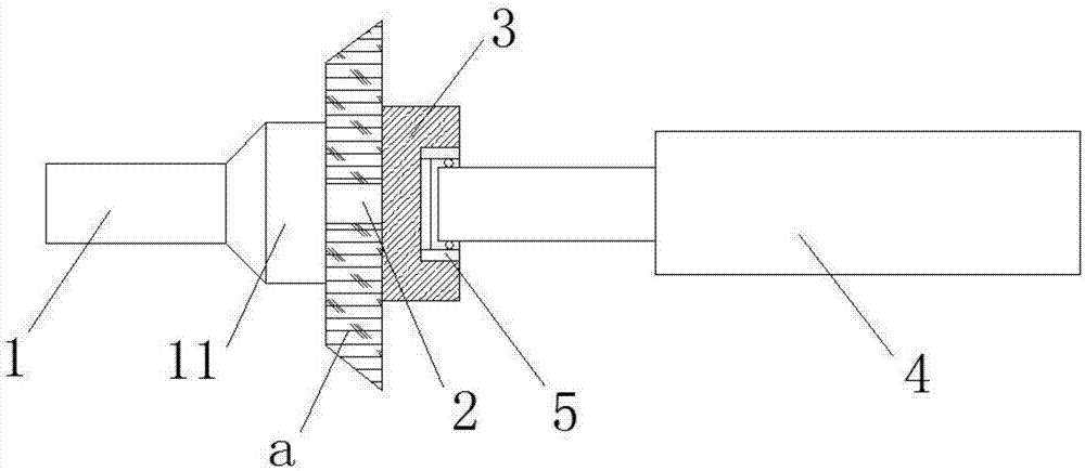
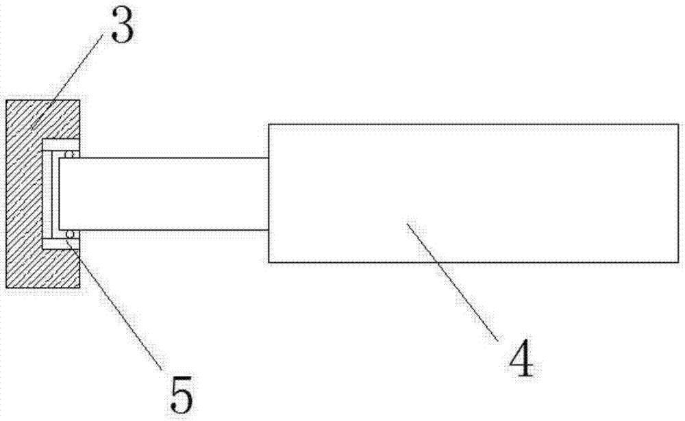
[0022] see figure 1 , figure 1 It is a structural schematic diagram of the rotary clamping assembly of the present invention. The rotary clamping assembly of the present invention includes a rotary shaft 1, a fixing member 2, a pressing block 3 and a pressing cylinder 4; the fixing member 2 is fixed on the rotating shaft 1 and is used to fix the workpiece a; the pressing The compression cylinder 4 is arranged coaxially with the rotary shaft 1, and the piston rod of the compression cylinder 4 faces the rotary shaft 1; the compression block 3 is fixed on the piston of the compression cylinder 4 through a bearing 5 On the rod, there is a gap between the pressing block 3 and the fixing piece 2 .

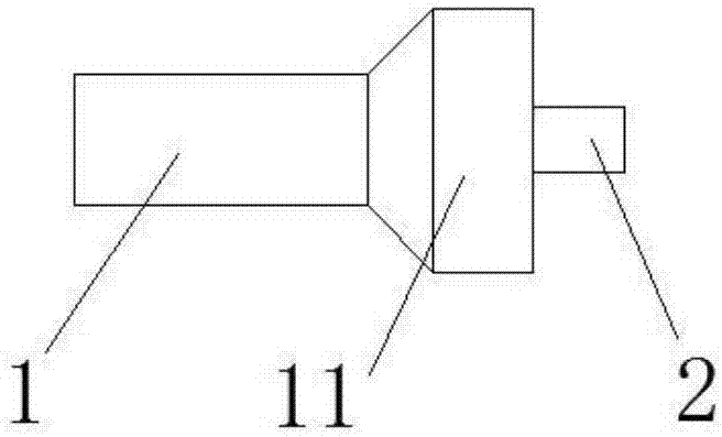
[0023] Specifically, see figure 2 , figure 2 It is a schematic diagram of the structure of the rotary shaft 1 and the fixed part 2. In this embodiment, a fixing part 11 is preferably provided at the end of the rotating shaft 1, the diameter of the fixing part 11 is larger than the...


PUM


Abstract

The invention relates to a rotary clamping assembly. The rotary clamping assembly comprises a rotary shaft, a fixed part, a pressing block and a pressing cylinder. The fixed part is fixed to the rotary shaft and used for fixing a machined part. The pressing cylinder and the rotary shaft are arranged coaxially. A piston rod of the pressing cylinder faces the rotary shaft. The pressing block is fixed to the piston rod of the pressing cylinder through a bearing. A gap is formed between the pressing block and the fixed part. According to the rotary clamping assembly, through arrangement of the rotary shaft, the fixed part, the pressing cylinder and the pressing block, the pressing block is fixed to the piston rod of the pressing cylinder through the bearing; the machined part is pressed onto the fixed part through the pressing block; the pressing force of the rotary clamping assembly is adjustable; the fixing precision of the machined part is high through the fixed part; and the machining precision is guaranteed.

Description

technical field [0001] The invention relates to the field of machining equipment, in particular to a rotary clamping assembly. Background technique [0002] When processing a rotary workpiece with a hole and the hole as the central axis (such as a grinding wheel), it is often connected with a shaft and fastened with screws, or a centrally expanding fixture (such as an inner three-jaw) is used. Products are fixed, and these fixing methods generally have some disadvantages. [0003] (1) Using fastening screws to connect, the disadvantage is that the clamping speed is too slow, which affects work efficiency. [0004] (2) Using the center expansion fixture, it is necessary to adjust the expansion amount, which is inefficient, and it is easy to affect the accuracy of the center hole due to poor force control, because the friction of the hole wall is the source of all the force for fastening the workpiece, so a relatively large force is required In order to improve the efficienc...

Claims


Application Information

Patent Timeline
Patent Type & Authority Applications(China)
IPC IPC(8): B23Q3/12
CPCB23Q3/12B23Q2703/04
Inventor 陈德庆
Owner 台山市兰宝磨具有限公司
Why Eureka
Try Eureka