
Improved environment-friendly dust removal device

A dust removal device and an improved technology, applied in gas treatment, chemical instruments and methods, membrane technology, etc., can solve the problems of loose plugging, health hazards, and inconvenient dust removal work, and achieve the purpose of preventing loose plugging and improving stability. Effect

Inactive Publication Date: 2017-11-21
XIAOGAN CITY KAPULONG DAILY NECESSITIES CO LTD
View PDF0 Cites 1 Cited by
  • Summary
  • Abstract
  • Description
  • Claims
  • Application Information

AI Technical Summary

Problems solved by technology

[0002] With the development of the industrial age, people's awareness of environmental protection is increasing. In the production of industrial products, a large amount of dust is generated. Without proper dust removal measures, the environment and air in the workshop will be polluted and deteriorated, which will be harmful to the human body. Health hazards, the existing dust removal equipment is generally used for industrial dust removal, but the mobility of the dust removal equipment is strong during the working process, through the existing plug-in power supply mode, although the plug-in is simple, its plug-in tightness is not high , will cause joint shaking with the movement of the dust removal equipment, resulting in loose plugs, unable to connect to the normal power supply, which will bring great inconvenience to the dust removal work and slow down the efficiency of dust removal. Therefore, in order to prevent the occurrence of loose plugs The final automatic locking is the premise to ensure the normal operation of the dust removal equipment

Method used


Image

  • Improved environment-friendly dust removal device
  • Improved environment-friendly dust removal device
  • Improved environment-friendly dust removal device

Examples


Embodiment Construction

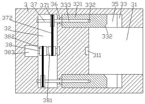
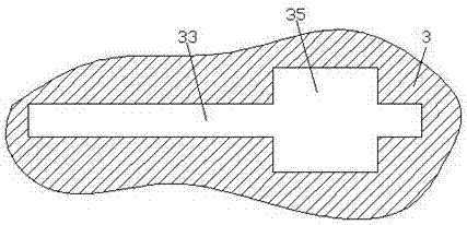
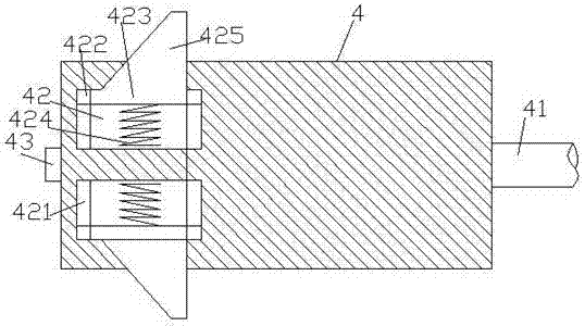
[0023] Such as Figure 1-Figure 7 As shown, an improved environmental protection dust removal device of the present invention includes a ring base 5, a box body 6 installed above the ring base 5, a telescopic block 622, an electrical connection part 3 arranged in the telescopic block 622 and Electric coupler 4, said ring seat 5 is equidistantly provided with fixing rings 52 around the outside, said fixing rings 52 are provided with fixing holes 53, said fixing holes 53 are provided with fixing bolts 531, said fixing rings Part 52 is used to fix the ring seat 5, so as to increase the firmness of the fixation; the right end surface of the electrical connection part 3 is provided with an insertion groove 31, and the upper and lower inner walls of the insertion groove 31 are correspondingly provided with locks. hole 35, the inside of the lock hole 35 is penetrated with a sliding connection groove 33 extended to both sides, and the electric connection part 3 on the left side of the...


PUM


Abstract

The invention discloses an improved environment-friendly dust removal device, which comprises a ring base, a box body installed above the ring base, a telescopic block, an electrical coupling part and an electrical coupling head arranged in the telescopic block, and equidistant around the outer side of the ring base. The fixing ring, the fixing hole is provided in the fixing ring, the fixing bolt is arranged in the fixing hole, the insertion groove is arranged in the right end surface of the electrical connection part, the upper and lower inner walls of the insertion groove are correspondingly provided with lock holes, and the inside of the lock hole is penetrated. There is a sliding connection groove extended to both sides. A transmission cavity is provided in the electrical connection part on the left side of the insertion groove. There is a stopper between the transmission cavity and the extension section on the left side of the sliding connection groove. The end is provided with a first transfer shaft, and the transmission cavity on the upper and lower sides of the first transfer shaft is correspondingly provided with a second transfer shaft extending to the left and right sides, and the extension section on the right side of the second transfer shaft passes through The stopper is penetrated and connected with the running fit, the push plate is connected with the slide fit in the sliding joint groove, the left end surface of the push plate is provided with a threaded hole, and the threaded thread in the threaded hole is connected with the first threaded rod; The invention has the advantages of simple structure, convenient operation, high locking stability and high safety.

Description

technical field [0001] The invention relates to the technical field of environmental protection dust removal, in particular to an improved environmental protection dust removal device. Background technique [0002] With the development of the industrial age, people's awareness of environmental protection is increasing. In the production of industrial products, a large amount of dust is generated. Without proper dust removal measures, the environment and air in the workshop will be polluted and deteriorated, which will be harmful to the human body. Health hazards, the existing dust removal equipment is generally used for industrial dust removal, but the mobility of the dust removal equipment is strong during the working process, through the existing plug-in power supply mode, although the plug-in is simple, its plug-in tightness is not high , will cause joint shaking with the movement of the dust removal equipment, resulting in loose plugs, unable to connect to the normal pow...

Claims


Application Information

Patent Timeline
Patent Type & Authority Applications(China)
IPC IPC(8): B01D49/00
CPCB01D49/00B01D2258/02
Inventor 陈斌
Owner XIAOGAN CITY KAPULONG DAILY NECESSITIES CO LTD
Learn More