Prefabricated beam transverse movement and vertical falling device and beam falling method

A prefabricated girder lateral movement, vertical drop technology, applied in the direction of bridges, bridge construction, erection/assembly of bridges, etc., can solve problems such as erection of public bridge erecting machines in place, difficulty in ensuring the stability of beams, and inability to use hoisting equipment. It achieves the effects of fewer auxiliary personnel, avoiding uneasy control and easy falling, and simple installation and debugging.

Pending Publication Date: 2017-11-17
SINOHYDRO BUREAU 7 CO LTD
View PDF7 Cites 2 Cited by
  • Summary
  • Abstract
  • Description
  • Claims
  • Application Information

AI Technical Summary

Problems solved by technology

However, due to the particularity of expressway planning limited by terrain and other conditions, such as the tunnel, the bridge-to-cave connection section, the ramp bridge, the small arc bridge, etc., cannot be erected in place by the highway public bridging machine due to the influence of the geographical environment, and affected by the environment restrictions, and it is not possible to use other hoisting equipment for construction
[0003] At present, simple tools such as manual gourds and steel rods are mostly used in domestic construction for lateral movement. It is difficult to ensure the stability of the beam body during horizontal movement and vertical installation, and the safety risk is extremely high, which is likely to cause safety accidents

Method used


Image

  • Prefabricated beam transverse movement and vertical falling device and beam falling method
  • Prefabricated beam transverse movement and vertical falling device and beam falling method
  • Prefabricated beam transverse movement and vertical falling device and beam falling method

Examples


Embodiment Construction

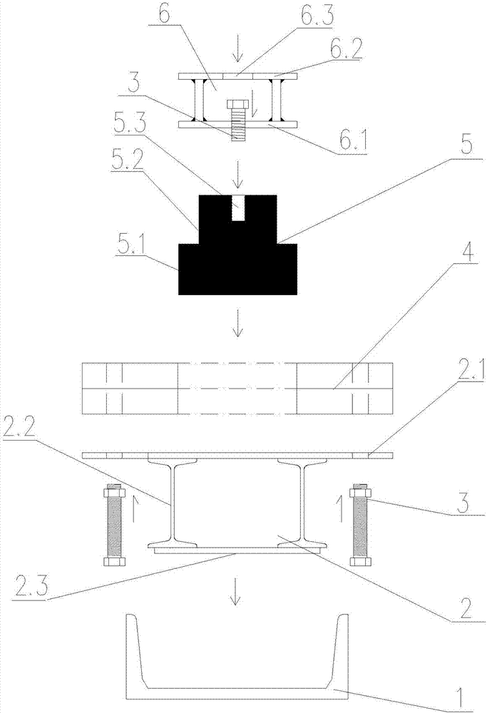
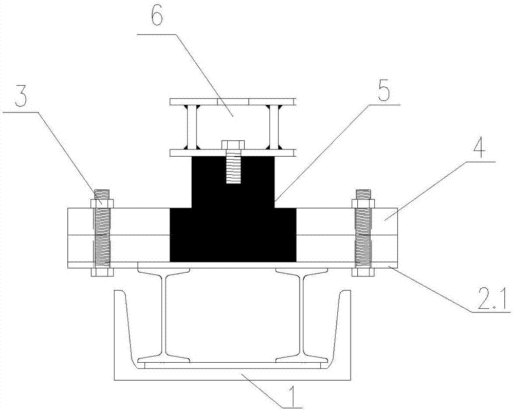
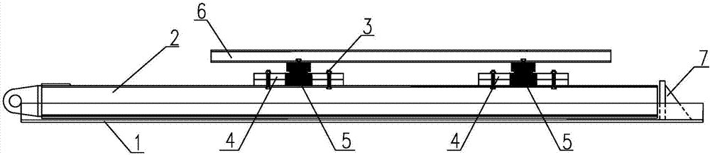
[0025] see Figure 1-Figure 3 , The device of the present invention includes a slide rail 1 and a slide beam 2, the slide rail 1 is placed on the cover beams on both sides of the prefabricated beam, and the slide beam 2 is placed in the slide rail 1. The key technology is to use high-strength bolts 3 on the sliding beam 2 to fix the vertical drop beam hydraulic jack slot 4 to ensure the stability of the prefabricated beam during the translation process, and to fix the thin-walled jack 5 on the vertical drop beam hydraulic jack slot 4. 5. Fix the prefabricated beam bottom support 6 for placing the prefabricated beam.

[0026] A limit baffle 7 is set at the end of the slide rail 1, which acts as a limit during the movement of the sliding beam 2 to ensure construction safety.

[0027] The sliding crossbeam 2 is welded with a bearing plate 2.1 at the upper end of two I-beams 2.2, and a sliding plate 2.3 at the lower end.

[0028] The prefabricated beam bottom bracket 6 is welded...


PUM


Abstract

The invention discloses a prefabricated beam transverse movement and vertical falling device and a beam falling method, belongs to the technical field of bridge project construction, and particularly relates to a device and a construction method for solving the problems that in tunnels, bridge and cave mouth connecting sections, small arc bridge, gate bridges and other construction parts where due to influences from the geographical environment, transverse movement and vertical erecting installation safety hidden danger is large. The device comprises a sliding rail and a sliding beam. The sliding beam is arranged in the sliding rail. A jack clamping groove is fixed to the sliding beam, a jack is fixed to the jack clamping groove, and a prefabricated beam bottom support is fixed to the jack. The prefabricated beam transverse movement and vertical falling device and the beam falling method have the beneficial effects that the jack is combined in the device, firstly, the system is vertically in an ascending state in the vertical direction, then a prefabricated beam horizontally slides to the to-be-erected position, finally, the system falls down in the vertical direction, and the prefabricated beam is erected on a bridge support. The device is high in stability, safe, reliable, easy to install and debug and suitable for transverse movement of prefabricated beams of various bridges at different parts, and the purpose of one-step completion of transverse movement and vertical beam falling erecting can be achieved.

Description

technical field [0001] The invention belongs to the technical field of bridge engineering construction, and is especially used to solve tunnels, bridge-to-cave connection sections, small arc bridges, gate bridges, etc., which cannot be erected normally due to the influence of geographical environment and have large safety hazards in lateral movement and vertical erection. The device and construction method of the construction site. Background technique [0002] With the rapid development of my country's expressway network, highway bridges, as the main measures for expressway crossing ditches and rivers and adjusting height differences, are the focus of expressway development. With the acceleration of domestic highway and bridge construction, precast concrete beams are more and more widely used because their manufacturing quality is easy to control and they are not affected by the construction period of the lower part of the bridge. However, due to the particularity of expre...

Claims


Application Information

Patent Timeline
Patent Type & Authority Applications(China)
IPC IPC(8): E01D21/00E01D21/06
CPCE01D21/00E01D21/06
Inventor 李旭东殷本林胡伟麟王再强姬海鹏郭晓陈旭东谢新华李成伟杨波袁怀
Owner SINOHYDRO BUREAU 7 CO LTD
Why Eureka
Try Eureka