A dml device capable of linear modulation

A linear modulation and device technology, applied in the field of optical communication, can solve the problems of high temperature power consumption, serious heat generation of DML optical transmitters, etc., and achieve the effects of less internal heat generation, high working efficiency, and fewer gold wire bonds.

Active Publication Date: 2019-09-10
GUANGXUN SCI & TECH WUHAN
View PDF6 Cites 0 Cited by
  • Summary
  • Abstract
  • Description
  • Claims
  • Application Information

AI Technical Summary

Problems solved by technology

[0010] The present invention mainly solves the problem of excessive high temperature and high power consumption of the existing DML light emitting component based on the PAM4 modulation mode, and proposes a DML light emitting component that can complete the linear modulation mode, which solves the problem of serious heating of the DML light transmitter. Can achieve a smaller, lower power design

Method used


Image

  • A dml device capable of linear modulation
  • A dml device capable of linear modulation
  • A dml device capable of linear modulation

Examples


Embodiment

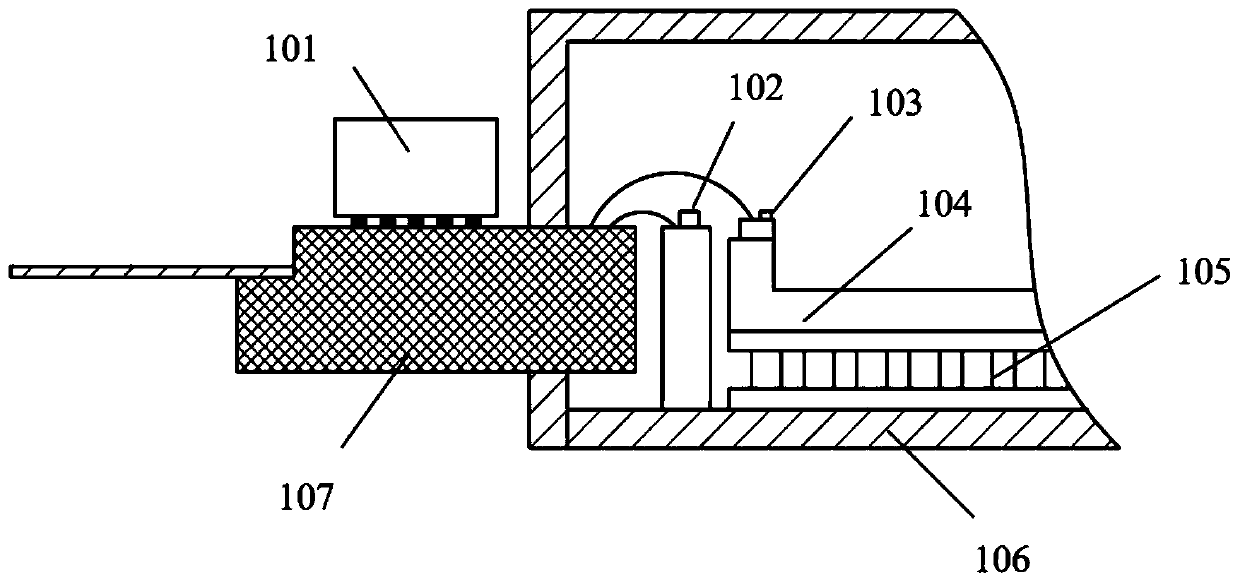
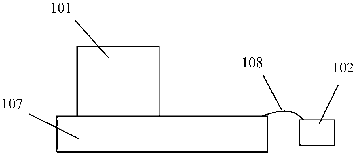
[0027] This embodiment is an integrated 200G DML TOSA optical device that can be used in the PAM4 modulation mode. The main components include a linear DML laser, a linear DML laser driver chip, a TEC and a PD array, and the like. The external circuit supplies power to the TOSA device through the PCB board and the soft tape, and the laser driver chip forms a link with the DML laser through the shell pins, bonding gold wire, etc.

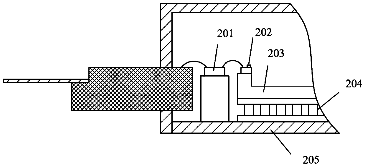
[0028] figure 2 Shown is a typical structural diagram of a traditional integrated DML device solution with a built-in laser driver chip. The laser driver chip 201 is located on the backlight surface of the DML laser chip 202 inside the package, and is connected to the external pins of the package and the laser by bonding gold wires. Among them, the laser chip and the laser chip driving circuit are internal heat sources of the device. Due to its own internal resistance, the laser driver chip will generate a lot of heat during operation, and more hea...


PUM


Abstract

The invention relates to a DML device, belongs to the technical field of optical communication, and in particular relates to a DML device capable of completing a linear modulation mode. The DML device provided by the invention selects a DML laser with a linear characteristic and a linear laser drive circuit with a signal calibration function; and meanwhile, the laser drive circuit is placed into a novel packaging structure at the outer part of a packaging tube shell, so that the problems that the DML optical transmitter is poor in linearity and serious in heating are solved, meanwhile, the device packaging device is simplified, and a more miniature design with lower power consumption can be achieved.

Description

technical field [0001] The invention relates to a DML device, which belongs to the technical field of optical communication, in particular to a DML device capable of completing a linear modulation mode. Background technique [0002] With the increasing popularity of big data, the demand for core network transmission bandwidth has been greatly increased every year. The current idea of ​​further improving the bandwidth mainly includes several aspects: increasing the signal rate, increasing the number of transmission links and adopting high-order modulation modes. Compared with the currently widely used NRZ modulation mode, under the same baud rate conditions, the transmission speed of PAM4 is twice that of NRZ. [0003] However, due to the characteristics of PAM4 modulation technology itself, under the same signal swing, PAM4 has higher noise requirements than NRZ, and PAM4 has higher signal linearity requirements than NRZ. Components (TOSA) put forward higher requirements. ...

Claims


Application Information

Patent Timeline
Patent Type & Authority Patents(China)
IPC IPC(8): H04B10/50H04B10/516H01S5/024H01S5/042
Inventor 徐红春邓磊梅雪丁深
Owner GUANGXUN SCI & TECH WUHAN
Why Eureka
Try Eureka