
Belt type drier feeding frame

A belt dryer and material feeding technology, which is applied in the direction of drying solid materials, drying, lighting and heating equipment, etc., can solve the problems of easy ejection of the conveyor belt, increase the workload of workers, and scattered medicinal materials on the ground, etc., to achieve the thickness of the material uniform effect

Inactive Publication Date: 2017-11-07
中山市程博工业产品设计有限公司
View PDF6 Cites 6 Cited by
  • Summary
  • Abstract
  • Description
  • Claims
  • Application Information

AI Technical Summary

Problems solved by technology

[0002] As we all know, medicinal materials are essential for human beings to treat diseases, and most of them are plants, some of which must be dehydrated and dried before they can be stored for a long time, and some even have stronger medicinal effects the longer they are stored. Most enterprises use belt dryers to dry For dehydration and drying of medicinal materials, the distance between the outlet of the roller feeding inlet and the conveyor belt of the traditional belt dryer is far away. When the medicinal materials enter the conveyor belt from the feeding inlet and outlet, it is easy to pop off the conveyor belt, causing some medicinal materials to be scattered on the ground, increasing the work of the workers. At the same time, because the place where the medicinal materials are scattered is close to the conveyor belt, it is dangerous when the workers pick up the medicinal materials, and most of the current feeding racks cannot achieve uniform feeding, so that the drying is not thorough enough, and a second step is required. drying job

Method used


Image

  • Belt type drier feeding frame
  • Belt type drier feeding frame
  • Belt type drier feeding frame

Examples


Embodiment Construction

[0014] The following will clearly and completely describe the technical solutions in the embodiments of the present invention with reference to the accompanying drawings in the embodiments of the present invention. Obviously, the described embodiments are only some, not all, embodiments of the present invention. Based on the embodiments of the present invention, all other embodiments obtained by persons of ordinary skill in the art without making creative efforts belong to the protection scope of the present invention.

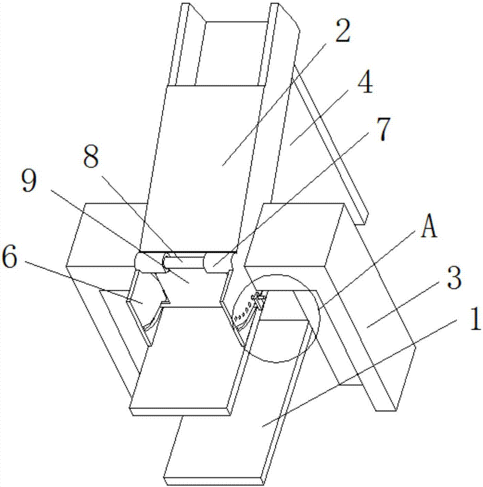
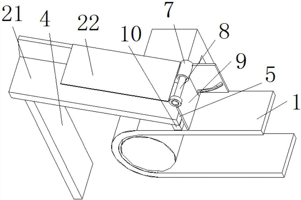
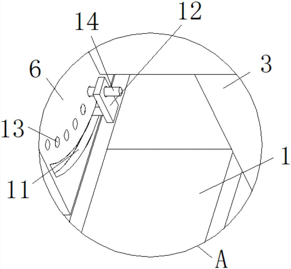
[0015] see Figure 1-3 , the present invention provides a technical solution: a belt dryer feed frame, including a conveyor frame 1 and a feed channel 2, the feed channel 2 includes an inclined bottom plate 21 and a top plate 22, and the length of the top plate 22 is shorter than that of the inclined bottom plate 21 The setting length is set so that the material can enter the conveyor belt smoothly, thereby preventing blockage. The feed channel 2 is set above ...


PUM


Abstract

The invention discloses a belt type drier feeding frame which comprises a conveying frame and a feeding channel. The feeding channel is formed above a conveying belt of the conveying frame. Side supports are arranged on the two sides of the feeding channel correspondingly. A rear supporting column is arranged at the rear side bottom end of each side support. Side baffles are arranged on the two sides, corresponding to the conveying belt, of the feeding channel. A discharging opening is formed in the portion, between the side baffles, of the feeding channel. The feeding channel comprises an oblique bottom plate and a top plate. The arrangement length of the top plate is smaller than the arrangement length of the oblique bottom plate. Connecting rings are arranged on the corresponding faces of the two side baffles. According to the belt type drier feeding frame, due to the design of the oblique bottom plate, materials in the feeding channel can fall onto the conveying belt smoothly. Meanwhile, the side baffles are arranged on the two sides, a lower baffle is arranged at the bottom end, and the materials can be prevented from falling. Meanwhile, by adjusting the position of an adjusting plate, thus, the charging thickness is controlled, and the materials on the conveying belt are uniform in thickness, and can be baked fully.

Description

technical field [0001] The invention relates to the technical field of a feed rack for a dryer, in particular to a feed rack for a belt dryer. Background technique [0002] As we all know, medicinal materials are essential for human beings to treat diseases, and most of them are plants, some of which must be dehydrated and dried before they can be stored for a long time, and some even have stronger medicinal effects the longer they are stored. Most enterprises use belt dryers to dry For dehydration and drying of medicinal materials, the distance between the outlet of the roller feeding inlet and the conveyor belt of the traditional belt dryer is far away. When the medicinal materials enter the conveyor belt from the feeding inlet and outlet, it is easy to pop off the conveyor belt, causing some medicinal materials to be scattered on the ground, increasing the work of the workers. At the same time, because the place where the medicinal materials are scattered is close to the ...

Claims


Application Information

Patent Timeline
Patent Type & Authority Applications(China)
IPC IPC(8): F26B25/00
Inventor 陈来胜陈伟景陈伟望
Owner 中山市程博工业产品设计有限公司
Learn More