


Quick Research
Generate reliable direction feasibility study reports for your R&D in just a few steps.

Technical Q&A
Discover and master advanced knowledge NOW. Basics, ideas, possibilities, all at once.

Find Solutions
As an expert in R&D theories, this can generate solutions to your technical problems instantly.

Evaluate Feasibility
Analyze your overall solution with one click, know your potential R&D risks in advance.

Monitor Landscape
Get weekly tech updates, stay abreast of the latest tech innovations and key insights.
Series decentralized deflection expansion joint
A tandem expansion joint technology, applied to bridge parts, bridges, buildings, etc., can solve the problems of single function reduction, complex structure, component fatigue, etc., to achieve improved safety and durability, simplified structure, maintenance and good replacement condition
- Summary
- Abstract
- Description
- Claims
- Application Information
AI Technical Summary
Problems solved by technology
Method used
Image

Examples
Embodiment 1
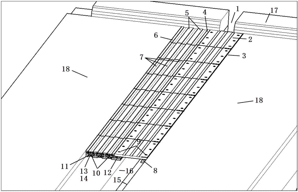
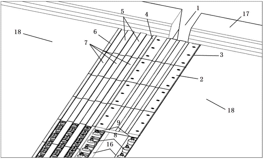
[0028] The series distributed displacement expansion joint 1 includes a cross-joint component, a displacement component and a sliding component. The displacement component is supported on the sliding component. A shallow structure connected in series after stretching and decomposing.
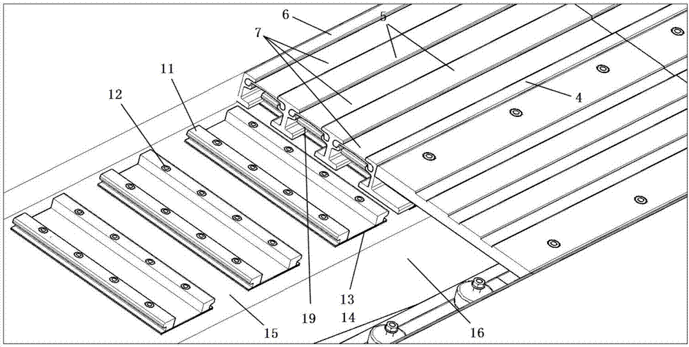
[0029] The seam-spanning assembly includes the seam-spanning plate 2, the fixed support side beam 3, the elastic support 8 and the compression bolt 9, and the displacement assembly includes the movable side beam 4, the movable middle beam 5, the guide rail hole 19, the fixed side beam 6 and the rubber seal The belt 7 and the sliding assembly include a control spring 10 , a guide rail 11 , a fixing bolt 12 , a slide plate 13 and an elastic pad 14 .
[0030] Both the fixed support side beam 3 and the movable side beam 4 are provided with an elastic support 8, one end of the span plate 2 is pre-pressed on the elastic support 8 on the fixed support side beam 3 with a compression bolt 9, and the othe...
Embodiment 2
[0034] In this embodiment, the seam-spanning board 2 is a square seam-spanning board, and other structures are the same as those in Embodiment 1.
[0035] During installation, the first step: positioning and bolting or welding to fix the supporting side beam 3, fixing the side beam 6 on the top surface of the beam body 15, positioning and setting the elastic cushion 14, the slide plate 13, the guide rail 11 and pressing the bolt with the fixing bolt 12 Connect; the second step: sequentially fit the movable center beam 5 and the movable side beam 4 to the holes; the third step: install the control spring 10 between the guide rail and the displacement assembly; the fourth step: sequentially fit the elastic support 8, span Seam the plate 2 and pre-press the connection with the compression bolt 9; the fifth step: install the rubber sealing belt 7.
[0036] Before installation, the necessary drainage facilities shall be constructed under the tandem distributed displacement expansio...
PUM
 Abstract
Description
Claims
Application Information
 - R&D Engineer
- R&D Manager
- IP Professional
- Industry Leading Data Capabilities
- Powerful AI technology
- Patent DNA Extraction
Browse by: Latest US Patents, China's latest patents, Technical Efficacy Thesaurus, Application Domain, Technology Topic, Popular Technical Reports.
© 2024 PatSnap. All rights reserved.Legal|Privacy policy|Modern Slavery Act Transparency Statement|Sitemap|About US| Contact US: help@patsnap.com