
Continuous weft insertion and overlock device based on three-dimensional loop knitting machine and its weft insertion method

A weaving machine and circular technology, which is applied in looms, textiles, textiles and papermaking, etc., can solve problems such as weaving failure, achieve the effects of improving work efficiency, increasing the success rate of weft insertion, and streamlining the weaving process

Active Publication Date: 2018-08-10
ZHEJIANG SCI-TECH UNIV
View PDF7 Cites 0 Cited by
  • Summary
  • Abstract
  • Description
  • Claims
  • Application Information

AI Technical Summary

Problems solved by technology

However, during the multiple reciprocating movements of the arrow shaft, due to the friction between the arrow shaft and the weft thread, the weft thread will be driven to move with the arrow shaft, so that the weft thread will exit the warp layer, which will lead to weaving failure

Method used

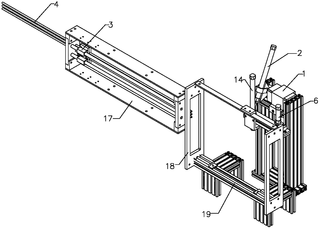
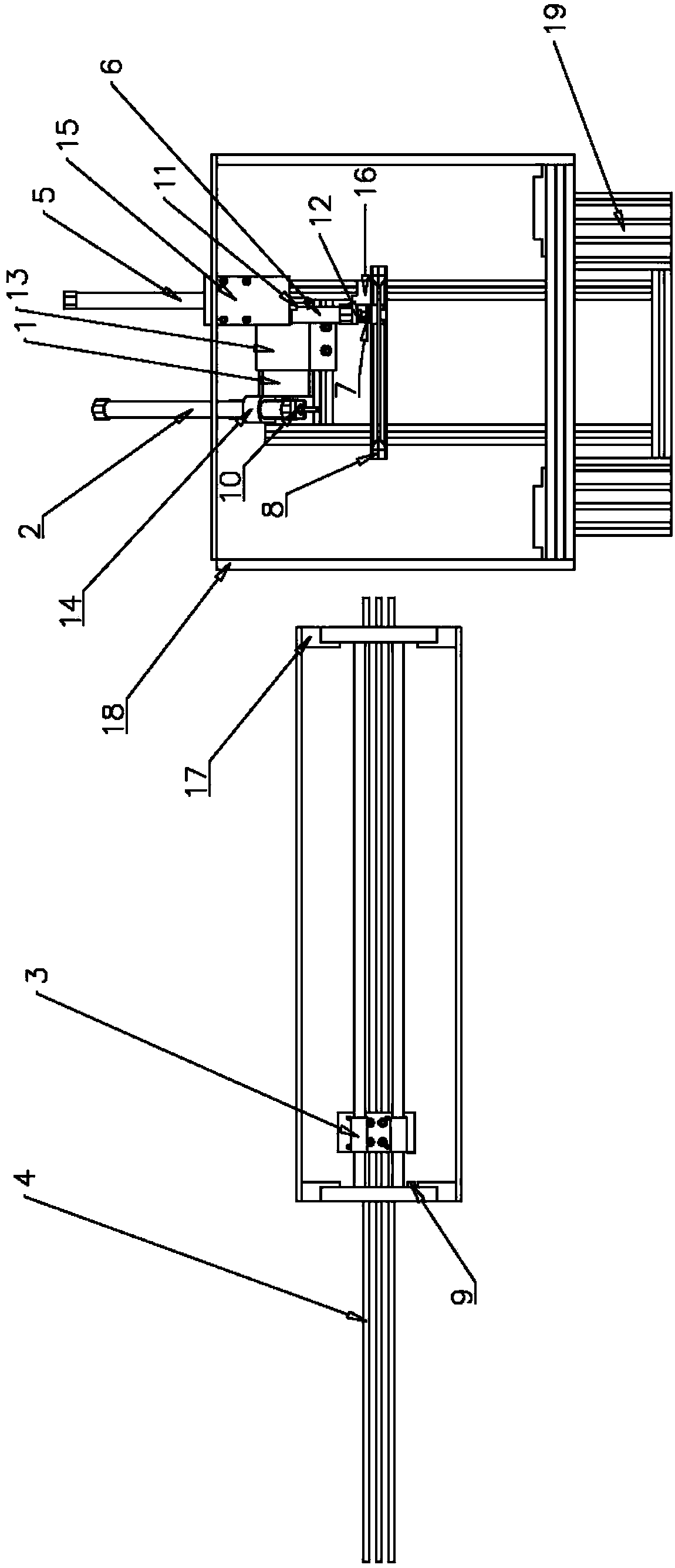

Image

  • Continuous weft insertion and overlock device based on three-dimensional loop knitting machine and its weft insertion method
  • Continuous weft insertion and overlock device based on three-dimensional loop knitting machine and its weft insertion method
  • Continuous weft insertion and overlock device based on three-dimensional loop knitting machine and its weft insertion method

Examples


Embodiment Construction

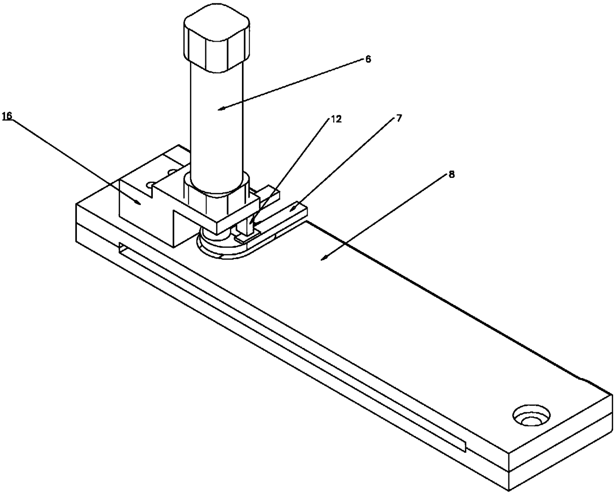
[0031] Please refer to the attached figure 1 To attach Figure 7 Shown, the present invention is a kind of continuous weft insertion locking device based on three-dimensional circular knitting machine, and it is made up of stepper motor 1, left locking cylinder 2, weft insertion arrow rod cylinder 3, arrow shaft 4, right locking cylinder 5. Right edge pressing cylinder 6, U-shaped pressing piece 7, weaving gap 8, arrow shaft laser distance measuring device 9, left edge locking laser ranging device 10, right edge locking laser ranging device 11, left edge pressing laser distance measuring device Device 12, stepping motor fixing part 13, left overlock cylinder fixing part 14, right overlock cylinder fixing part 15, right side pressing fixing part 16, arrow shaft and cylinder fixing part 17, beating-up heald frame 18, frame 19 And so on several parts.

[0032] Wherein, the stepping motor 1 is installed on the stepping motor fixing part 13, which is connected to and drives the l...


PUM


Abstract

The invention relates to a continuous weft and edge locking device and a weft insertion method based on a three-dimensional circular knitting machine. A stepping motor is connected to drive the left edge locking cylinder to rotate; the left edge locking cylinder is installed on a fixing part of the left edge locking cylinder; the left edge locking The laser distance measuring device monitors the stroke of the piston rod of the left seam cylinder; the right seam cylinder is installed on the fixing part of the right seam cylinder; the stroke of the right seam laser distance measuring device and the piston rod of the right seam cylinder; the weft insertion arrow The rod cylinder and the arrow shaft are respectively installed on the arrow shaft and the cylinder fixing part; the laser distance measuring device of the arrow shaft monitors the stroke of the arrow shaft; , which is connected to the U-shaped pressing piece; the U-shaped pressing piece is pressed against the weaving fell; the weaving fell is located on the frame; the left edge laser distance measuring device monitors the stroke of the weaving fell. The weft thread locking device of the present invention fixes the outer weft threads of the warp yarn layer, thereby avoiding the movement of the weft threads caused by the reciprocating motion of the arrow shaft, and improving the success rate of weft insertion.

Description

【Technical field】 [0001] The invention relates to a component device of a three-dimensional circular knitting machine, in particular to a continuous weft insertion and edge locking device based on the three-dimensional circular knitting machine, which belongs to the technical field of textile machinery. 【Background technique】 [0002] Three-dimensional fabrics are used as reinforcement materials for composite structures, and three-dimensional orthogonal fabrics constrain the thickness direction by binding yarns, thus avoiding the problem of easy delamination of laminated fabrics. The three-dimensional loom is used to weave three-dimensional orthogonal fabrics. In this equipment, the weft weaving of the three-dimensional woven fabric is realized through the side weft insertion device, and the weft yarn enters the warp layer through the continuous reciprocating movement of the arrow shaft to complete the three-dimensional fabric weaving. Among them, we refer to the weft yarn t...

Claims


Application Information

Patent Timeline
Patent Type & Authority Patents(China)
IPC IPC(8): D03D47/40D03D47/12
CPCD03D47/12D03D47/40
Inventor 吴震宇张利旵汪茂林应志平
Owner ZHEJIANG SCI-TECH UNIV
Learn More