
Desulfurization tower defogging device and desulfurization and dust removal device

A demisting device, desulfurization and dust removal technology, applied in the field of desulfurization tower demisting device and desulfurization and dust removal device, can solve the problems of tower resistance increase, waste of manpower and material resources, demisting efficiency, desulfurization efficiency decline, etc., and achieve good results Effect

Inactive Publication Date: 2017-11-03
SHANDONG TIANLI ENERGY SAVING ENG
View PDF5 Cites 3 Cited by
  • Summary
  • Abstract
  • Description
  • Claims
  • Application Information

AI Technical Summary

Problems solved by technology

However, because the suspended sulfur entrained in the gas will adhere to the surface of the mist trapping packing, after long-term accumulation to a certain thickness, the tower resistance will increase, the demisting efficiency and desulfurization efficiency will drop sharply, and even the tower will be blocked.
In actual production, it is necessary to stop production frequently, manually enter the tower to clean the mist trap packing, or even replace the mist trap packing, resulting in huge waste of manpower and material resources, seriously affecting the normal operation of the desulfurization process

Method used


Image

  • Desulfurization tower defogging device and desulfurization and dust removal device
  • Desulfurization tower defogging device and desulfurization and dust removal device
  • Desulfurization tower defogging device and desulfurization and dust removal device

Examples


Embodiment 1

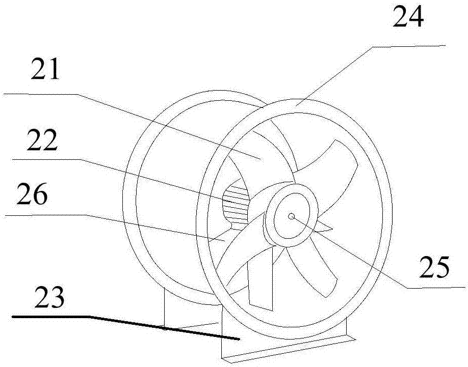
[0033] figure 1 The structural schematic diagram of the desulfurization tower demisting device 1 provided for the embodiment of the present invention, as figure 1As shown, the desulfurization tower defogging device 1 provided by the embodiment of the present invention is used to defog the gas discharged from the desulfurization tower. And the exhaust fan 2, the defogging part 102 is an annular structure formed by a plurality of blades 103, and its inner ring diameter is 1 / 6-1 / 4 of the diameter of the ventilation pipe 101, and the outer ring of the defogging part 102 and the ventilation pipe 101 The inner surface of the air duct 101 is connected, and a plurality of blades 103 are divergently distributed in the shape of a clockwork wheel, and they are all inclined in the same direction. The angle between the blade surface of the blade 103 and the cross section of the ventilation pipe 101 is in the range of 60°-80°. There are multiple defogging components 102, which are respecti...

Embodiment 2

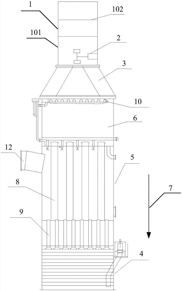
[0042] image 3 The desulfurization and dust removal device provided for the embodiment of the present invention, such as image 3 As shown, the desulfurization and dust removal device provided by the embodiment of the present invention includes a multi-stage filter tower and the desulfurization tower demist device 1 of the above technical solution, and the desulfurization tower demist device 1 is connected to the top of the multi-stage filter tower.

[0043] Furthermore, the desulfurization and dust removal device can be a complete shell, which is divided into different functional sections through different structural bodies. Alternatively, it can also be formed by connecting independent functional sections with different processing capabilities through welding, riveting and other means.

[0044] The desulfurization and dust removal device provided by the embodiment of the present invention includes a multi-stage filter tower and the demist removal device 1 of the above-ment...


PUM

PropertyMeasurementUnit
Angleaaaaaaaaaa

Abstract

The invention provides a desulfurization tower defogging device and a desulfurization and dust removal device, and relates to the technical field of environmental protection equipment. The desulfurization tower defogging device provided by the invention is arranged on the top of a desulfurization tower, and comprises a ventilating pipe, defogging components and an exhaust fan, wherein each defogging component is of a ring structure formed by blades, the diameter of the inner ring of each defogging component is one sixth to one fourth of the diameter of the ventilating pipe, so a center hole can better discharge liquid in gas, if the center hole is too large, the discharge is not complete enough, and if the center hole is too small, the discharge is difficult to realize. The outer ring of each defogging component is connected with the inner surface of the ventilating pipe, the blades are divergently distributed like spokes of a wheel, the blades are placed obliquely, and an angle formed by the surface of each blade and the cross section of the ventilating pipe is 60 to 80 degrees. Such a stacking method can well keep liquid drops off. A plurality of defogging components are arranged, several defogging operations can be conducted, and the effect is better.

Description

technical field [0001] The invention relates to the technical field of environmental protection equipment, in particular to a demisting device for a desulfurization tower and a desulfurization and dust removal device. Background technique [0002] In recent years, the construction of coal-fired power plants in my country has experienced a peak period. On the one hand, the capacity and parameters of the units have been continuously improved, and a large number of new power generation technologies have been applied to coal-fired units; on the other hand, as the society's environmental protection requirements continue to increase, Pollutant emission standards for coal-fired power plants have become increasingly stringent. For the SOx pollutants contained in the flue gas of coal-fired power plants, my country mainly adopts wet desulfurization technology for control. This technology is relatively mature and reliable, and plays an important role in the control of flue gas SOx emis...

Claims


Application Information

Patent Timeline
IPC IPC(8): B01D53/80B01D53/50B01D53/75B01D53/26B01D47/06B01D50/00
CPCB01D53/80B01D47/06B01D50/00B01D53/26B01D53/50B01D53/75B01D2247/10
Inventor 刁志芹刁志峰张文学
Owner SHANDONG TIANLI ENERGY SAVING ENG
Learn More