fuel injection valve
A fuel injection valve and fuel technology, which is applied to fuel injection devices, charging systems, machines/engines, etc., can solve the problems of insufficient acceleration, poor fuel spray atomization, and poor layout, and reduce the dead zone volume. , The processability is improved, the effect of large jet flow rate
- Summary
- Abstract
- Description
- Claims
- Application Information
AI Technical Summary
Problems solved by technology
Method used
Image
Examples
Embodiment approach 1
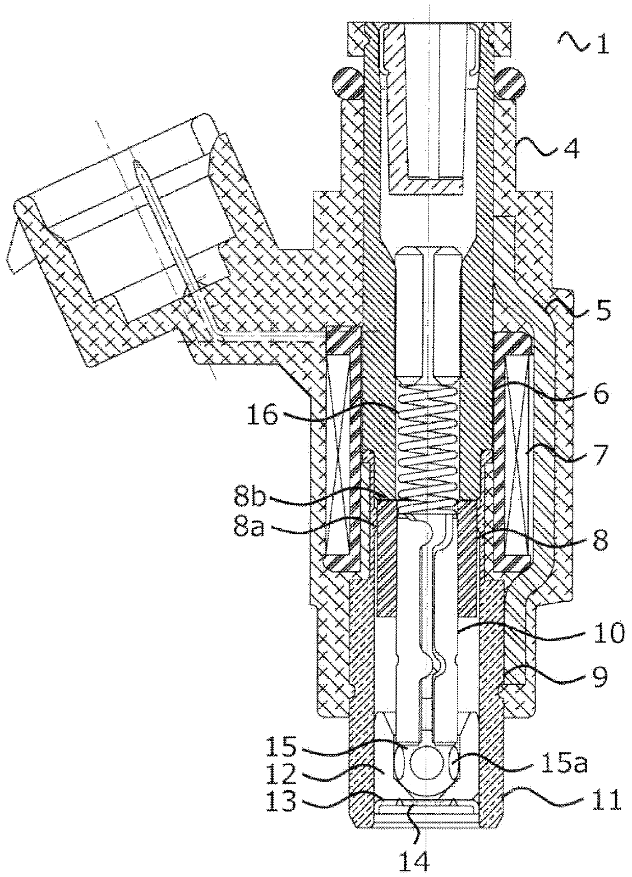
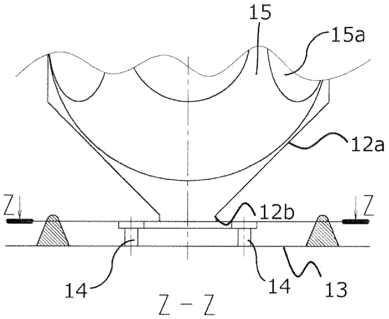
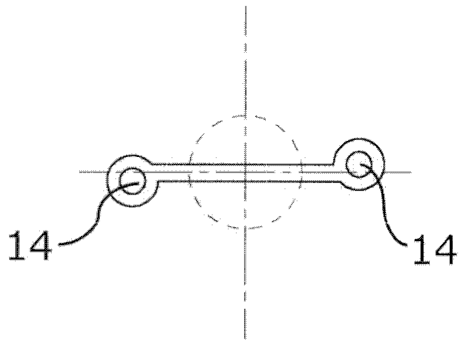
[0049] figure 1 A cross-sectional view of the fuel injection valve according to Embodiment 1 is shown in . Figure 2A , Figure 2B , image 3 , Figure 4 The front end portion of the fuel injection valve according to Embodiment 1 is shown, where Figure 2A A cross-sectional view of the front end is shown in the Figure 2B The top view is shown in the image 3 An enlarged view of the top view is shown in the Figure 4 The dimensional relationship in top view is shown in . In the figure, symbol 1 denotes a fuel injection valve, symbol 4 denotes a solenoid device, symbol 5 denotes a yoke portion of a magnetic circuit, that is, a housing, symbol 6 denotes a fixed iron core portion of a magnetic circuit, that is, an iron core, symbol 7 denotes a coil, and symbol 8 is a movable iron core portion of the magnetic circuit, that is, an armature, and 9 is a valve device, and the valve device 9 is composed of a valve core 10 , a valve main body 11 and a valve seat 12 . The valve m...
Embodiment approach 2
[0061] Figure 8 The front end portion of the fuel injection valve according to Embodiment 2 is shown in . In order to achieve atomization of fuel spray, it is important to form a thin and uniform liquid film along the inner wall of the injection hole, but once the swirling flow generated at the injection hole 14 is deflected, the liquid film formed on the inner wall of the injection hole will be partially become thicker and may impair micronization performance. Therefore, in Embodiment 2, there is provided the second fuel introduction path 21 for introducing fuel into the swirl chamber 17 from a direction different from that of the fuel introduction path 18 . At this time, at a position where the swirl direction of the fuel flowing into the swirl chamber 17 from the fuel introduction path 18 is the same as the swirl direction of the fuel flowing into the swirl chamber 17 from the second fuel introduction path 21, the fuel introduction path 18 and the The second fuel introdu...
Embodiment approach 3
[0065] Figure 9 The front end portion of the fuel injection valve according to Embodiment 3 is shown in . When two fuel introduction paths are provided for one swirl chamber, the relative angle of the two fuel introduction paths is about 180°, and the thickness of the liquid film formed on the inner wall of the injection hole 14 is Uniformity is best. Therefore, in the third embodiment, the thickness of the liquid film formed on the inner wall of the injection hole 14 is made more uniform by connecting the fuel introduction path 18 and the second fuel introduction path 21 with the swirl chamber 17 from directions opposite to each other, so that the fuel The degree of micronization of the spray is better.
[0066] In addition, in Figure 9 In the illustrated configuration, the fuel introduction path 18 and the communication portion of the second fuel introduction path 21 that communicates with the valve seat opening are shared. The dead volume is reduced by sharing the com...
PUM
 Abstract
Description
Claims
Application Information
 - R&D Engineer
- R&D Manager
- IP Professional
- Industry Leading Data Capabilities
- Powerful AI technology
- Patent DNA Extraction
Browse by: Latest US Patents, China's latest patents, Technical Efficacy Thesaurus, Application Domain, Technology Topic, Popular Technical Reports.
© 2024 PatSnap. All rights reserved.Legal|Privacy policy|Modern Slavery Act Transparency Statement|Sitemap|About US| Contact US: help@patsnap.com


