Eureka AIR delivers breakthrough ideas for toughest innovation challenges, trusted by R&D personnel around the world.

Sliding-block internal plastic filling structure

A sliding block and glue feeding technology, applied in the field of mold structure, can solve the problems of glue leakage and inability to feed glue, and achieve the effect of avoiding glue leakage and facilitating processing.

Active Publication Date: 2017-10-31
MITAC PRECISION TECH(KUNSHAN) CORP
View PDF2 Cites 2 Cited by
  • Summary
  • Abstract
  • Description
  • Claims
  • Application Information

AI Technical Summary

Problems solved by technology

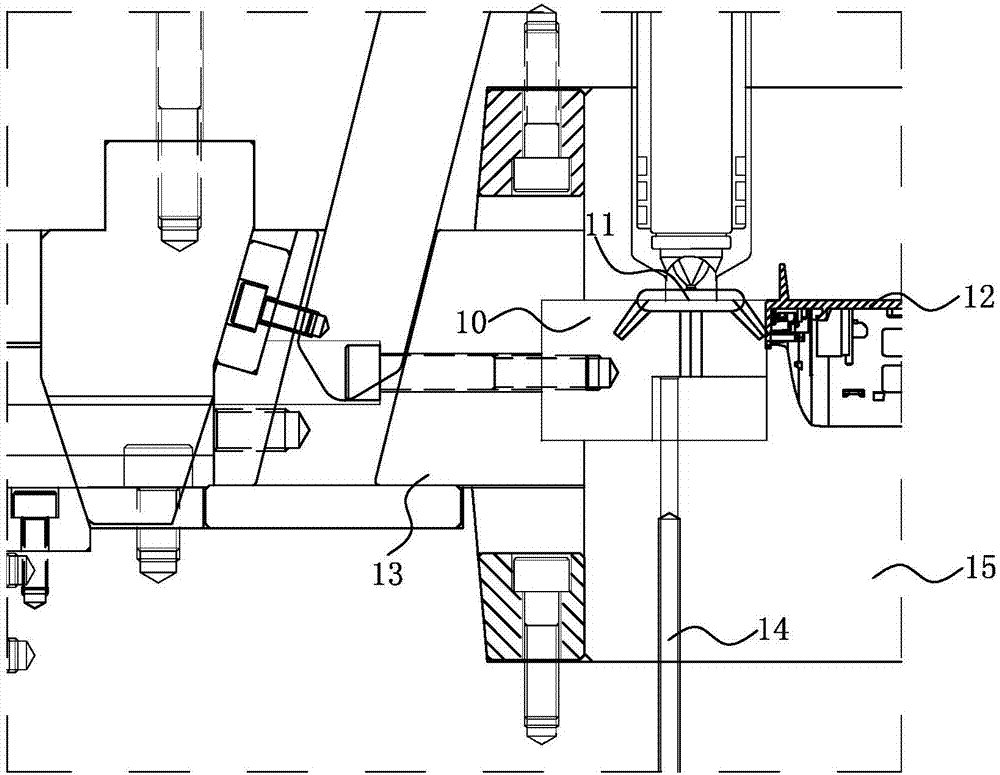
However, this type of latent glue-feeding structure in the slider will cause the problem of glue leakage due to the back and forth friction between the slider insert 10 and the male mold core 15
[0004] In view of this, it is necessary to develop an inner glue feeding structure of the slider to solve the above-mentioned problem that the outer surface of the plastic product in the prior art cannot be glued, and the slider insert rubs against the male mold core, resulting in glue leakage.

Method used


Image

  • Sliding-block internal plastic filling structure
  • Sliding-block internal plastic filling structure
  • Sliding-block internal plastic filling structure

Examples


Embodiment Construction

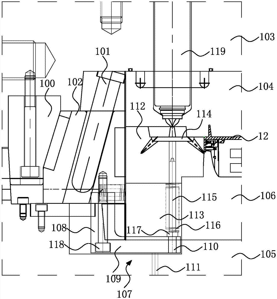
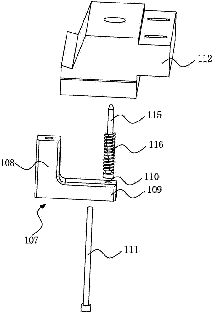
[0022] see figure 2 and image 3 shown, where figure 2 A schematic diagram of the sliding block glue feeding structure of the present invention in the mold clamping state is drawn, image 3 A three-dimensional exploded schematic diagram of a partial structure in the glue-feeding structure of the slider of the present invention is shown.

[0023] In this embodiment, the inner glue feeding structure of the slider of the present invention is applied to a plastic product 12 whose exterior surface cannot be glued into a mold. The mold includes a slider bundle 100, an inclined guide post 101, and a slider body 102. , female template 103, female mold core 104, male template 105, male mold core 106, upper ejector plate and lower ejector plate (not shown in the figure), the inner glue feeding structure of the slider includes:

[0024] Support block 107, it is located in male formwork 105 and is provided with movement stroke between male formwork 105, described support block 107 ha...


PUM


Abstract

The invention discloses a sliding-block internal plastic filling structure. The sliding-block internal plastic filling structure comprises a supporting block, an ejector pin, a sliding block insert core, a pulling pin and an elastic element; the supporting block is provided with a first supporting arm and a second supporting arm which are arranged to form an right angle, the first supporting arm is connected with a sliding block body, and the second supporting arm is provided with a vertical hole; one end of the ejector pin is fixed to the interior of an upper ejector plate, the other end of the ejector pin abuts against the second supporting arm, and the other end of the ejector pin and the vertical hole are arranged in a staggered mode; the sliding block insert core is connected with the sliding block body, a male mold core and a female mold core are each internally provided with a through groove, and the sliding block insert core is internally provided with a vertical runner for achieving plastic filling molding of a plastic product; one end of the pulling pin is arranged on the second supporting arm and vertically corresponds to the vertical hole, and the other end of the pulling pin penetrates through the through grooves to stretch into the sliding block insert core to abut against the vertical runner; and the elastic element sleeves a segment of outer edge, penetrating through the through grooves, of the pulling pin. According to the sliding-block internal plastic filling structure, plastic filling is achieved through the sliding block insert core from one side face of the plastic product, the structure is suitable for the plastic product of which the appearance face can not achieve plastic filling, and the friction plastic leakage problem of the sliding block insert core and the mold cores is avoided; the mold internal plastic filling structure is low in machining difficulty and machining precision requirement and convenient to machine.

Description

【Technical field】 [0001] The invention relates to a mold structure, in particular to a glue-feeding structure inside a slider. 【Background technique】 [0002] When some plastic products are injection molded, it is necessary to use sliders to form from the four sides of the plastic product. At this time, if the outer surface of the plastic product cannot be glued, one molding method is: the mold for forming the plastic product needs to be poured into the mold, and the glue is fed from the side of the plastic product, but in this way, a hydraulic cylinder that is poured into the mold is required Components, mold structures are particularly complex. [0003] In order to overcome the disadvantages of reverse injection molding and complex mold structure, another molding method in the prior art is: adopting a latent glue-feeding structure in the slider. see figure 1 As shown, it depicts the latent glue feeding structure in the slider in the prior art. By setting the vertical fl...

Claims


Application Information

Patent Timeline
IPC IPC(8): B29C45/33
CPCB29C45/33
Inventor 郭行
Owner MITAC PRECISION TECH(KUNSHAN) CORP
Why Eureka
Eureka Blog
Learn More