Resin molding apparatus and resin molding method
A resin molding and resin technology, applied in the field of resin molding devices, can solve the problems of residual resin scattering, pollution, and excessive time.
- Summary
- Abstract
- Description
- Claims
- Application Information
AI Technical Summary
Problems solved by technology
Method used
Image


Examples
Embodiment approach 1
[0045] (Structure of resin molding equipment)
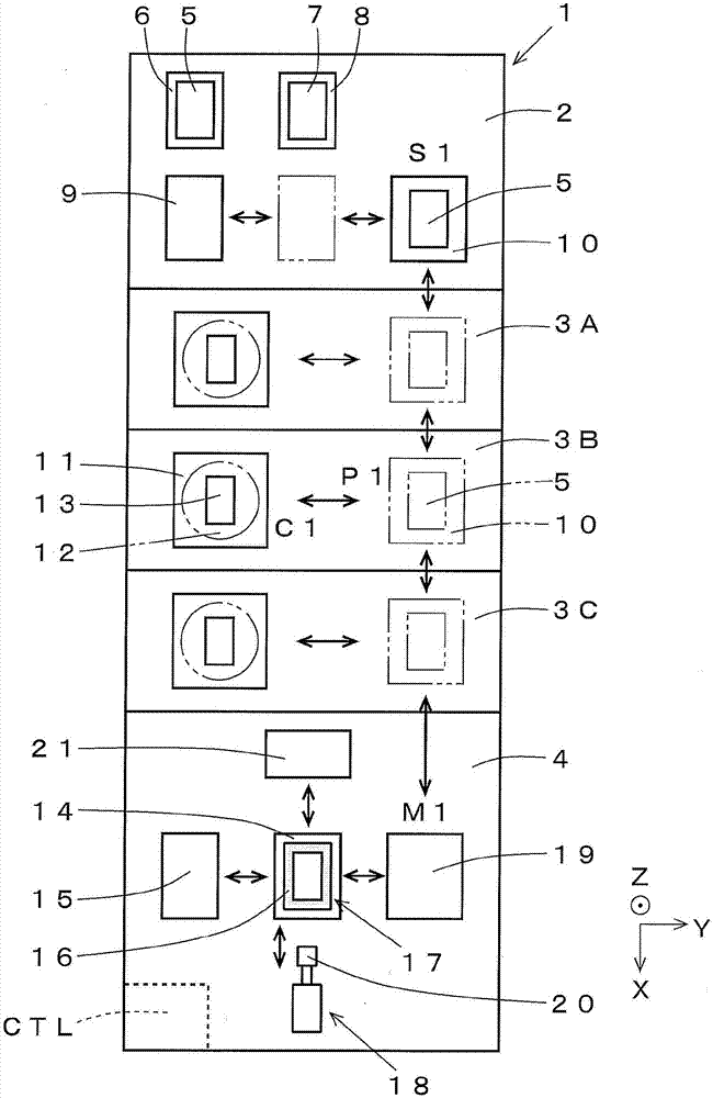
[0046] Reference figure 1 The structure of the resin molding apparatus of the present invention will be described. figure 1 The resin molding apparatus 1 shown is a resin molding apparatus using a compression molding method. An example in which liquid resin that is a fluid resin is used as the resin material is shown.
[0047] The resin molding apparatus 1 includes a substrate supply storage module 2, three molding modules 3A, 3B, 3C, and a resin supply module 4 as constituent elements, respectively. The substrate supply storage module 2, the molding modules 3A, 3B, 3C, and the resin supply module 4, which are structural elements, can be attached to and detached from each other with respect to other structural elements, and can be replaced.
[0048] The substrate supply and storage module 2 is provided with: a pre-packaged substrate supply part 6, which supplies the pre-packaged substrate 5; a post-package substrate accommodating par...
Embodiment approach 2
[0112] (Structure of resin removal mechanism)
[0113] Reference Figure 5 Next, another form of the resin removing mechanism used in the resin molding apparatus 1 will be described. The difference from Embodiment 1 is that a rotating body is used as a member for removing the residual resin 30 instead of a film-shaped member as a member for removing the residual resin 30. Since the structure other than the resin removing mechanism is completely the same as that of the first embodiment, the description is omitted.
[0114] Such as Figure 5 As shown, the resin removal mechanism 35 includes: a rotating body 36 for attaching and winding the residual resin 30; a rotating mechanism 37 (the part shown by a dotted line in the figure) for rotating the rotating body 36; and a container 38 for storing the residual resin Resin 30. As the rotating body 36, for example, a rotating body having a circular cross-sectional shape can be used. The storage container 38 is provided with a scraper-sh...
Embodiment approach 3
[0134] (Structure of hose for resin injection)
[0135] Reference Figure 7 The resin injection hose used in the dispenser 18 as the resin injection mechanism will be described.
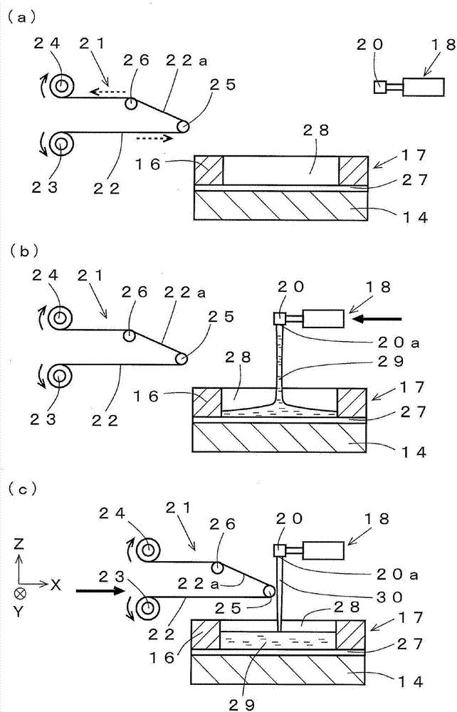
[0136] Such as Figure 7 As shown, an elastically deformable hose 40 is provided on the lower surface of the resin injection portion 20 of the dispenser 18 via a joint (not shown). The liquid resin is sprayed downward from the tip of the hose 40. The hose 40 is attachable to and detachable from the resin injection part 20 via a joint, and the hose 40 can be replaced. The hose 40 having a different inner diameter or shape can be selected and used in accordance with the product or application. As the hose 40, for example, a hose formed of silicone rubber or the like can be used. The hose 40 may be a material that can be elastically deformed.
[0137] A clamping mechanism 41 that squeezes the flow path of the hose 40 is provided around the hose 40. The flow path of the hose 40 can be narrowed by the clamp...
PUM
 Abstract
Description
Claims
Application Information
 - R&D
- Intellectual Property
- Life Sciences
- Materials
- Tech Scout
- Unparalleled Data Quality
- Higher Quality Content
- 60% Fewer Hallucinations
Browse by: Latest US Patents, China's latest patents, Technical Efficacy Thesaurus, Application Domain, Technology Topic, Popular Technical Reports.
© 2025 PatSnap. All rights reserved.Legal|Privacy policy|Modern Slavery Act Transparency Statement|Sitemap|About US| Contact US: help@patsnap.com