
Display panel and display device

A display panel and substrate substrate technology, which is applied in the direction of static indicators, instruments, organic semiconductor devices, etc., can solve the problems of affecting the display effect of the folding area, damage, and affecting the display effect of the display panel, etc.

Active Publication Date: 2017-10-24
SHANGHAI TIANMA MICRO ELECTRONICS CO LTD
View PDF7 Cites 56 Cited by
  • Summary
  • Abstract
  • Description
  • Claims
  • Application Information

AI Technical Summary

Problems solved by technology

However, multiple small flexible display screens are spliced ​​together to form a foldable display panel, and then applied to large display devices. This splicing method is aimed at small display devices, such as mobile phones, tablet computers, etc. The effect is not ideal, which affects the display effect of the entire display panel
[0004] In addition, when the display panel is a flexible display panel, when the bending radius is large, the pixel circuit in the display panel and the surrounding shift register can also achieve the bending effect without designing bending resistance. In small cases, the semiconductor devices in the pixel circuit and the surrounding shift register may be damaged due to the influence of the degree of bending, thus affecting the display effect of the folded area
[0005] Therefore, in the prior art, the display panel with the folded area has affected the display effect of the display panel due to the structural characteristics of the pixel circuit.

Method used


Image

  • Display panel and display device
  • Display panel and display device
  • Display panel and display device

Examples


Embodiment Construction

[0040] In order to make the above objects, features and advantages of the present invention more comprehensible, the present invention will be further described below in conjunction with the accompanying drawings and embodiments. Example embodiments may, however, be embodied in many forms and should not be construed as limited to the embodiments set forth herein; rather, these embodiments are provided so that this disclosure will be thorough and complete, and will fully convey the concept of example embodiments to those skilled in the art. The same reference numerals denote the same or similar structures in the drawings, and thus their repeated descriptions will be omitted. The words expressing position and direction described in the present invention are all described by taking the accompanying drawings as an example, but changes can also be made according to needs, and all changes are included in the protection scope of the present invention. The accompanying drawings of th...


PUM


Abstract

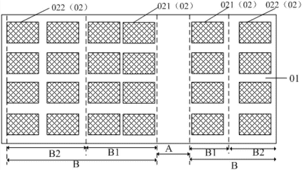
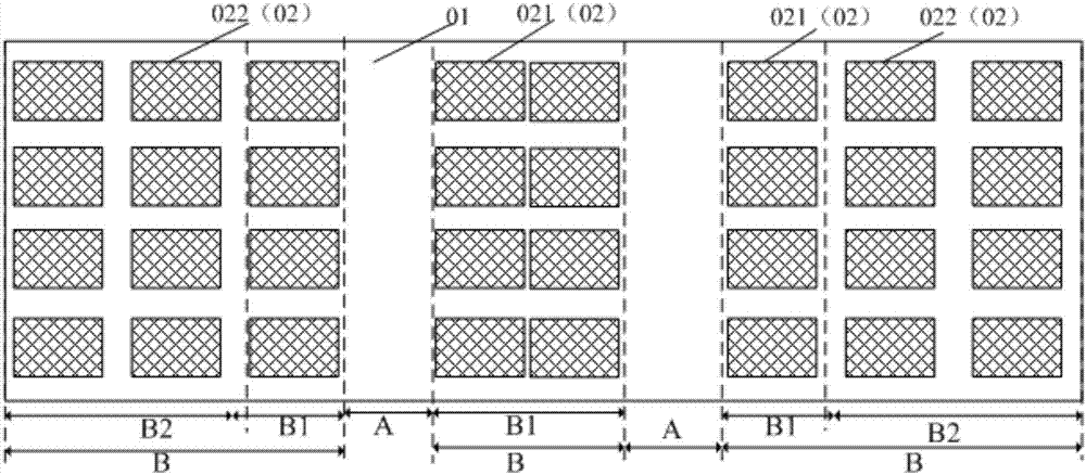
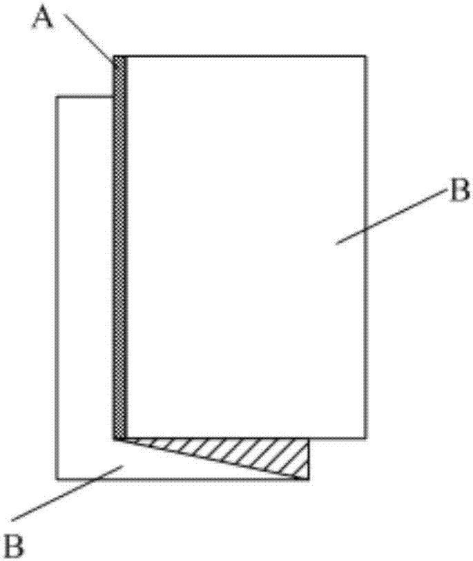
The present invention discloses a display panel and a display device. The invention aims to improve the bending resistance of the display panel without affecting the display effect of the display panel. The display panel is divided into at least one folding region and at least one non-folding region adjacent to the folding region; and the display panel comprises a substrate, a plurality of light emitting devices and a plurality of pixel circuit units, wherein the pixel circuit units are located on the substrate and are all arranged in the non-folding regions, wherein each non-folding region comprises at least one first region and at least one second region; each of the first regions and the second regions includes a plurality of pixel circuit units arranged in an array; the first regions are adjacent to the folding regions; the second regions are located at one side of each of the first regions which is far away from the folding regions; and the distribution density of the pixel circuit units in the first regions is greater than or equal to the distribution density of the pixel circuit units in the second regions.

Description

technical field [0001] The present invention relates to the field of display technology, in particular to a display panel and a display device. Background technique [0002] The display device with foldable performance is convenient to carry, and is an important development direction of the display device in the future. [0003] At present, for the manufacturing scheme of foldable display devices, it is generally to splice a plurality of small display screens together to form a complete display panel, and the splicing part is used as a foldable area. However, multiple small flexible display screens are spliced ​​together to form a foldable display panel, and then applied to large display devices. This splicing method is aimed at small display devices, such as mobile phones, tablet computers, etc. The effect is not ideal, thereby affecting the display effect of the entire display panel. [0004] In addition, when the display panel is a flexible display panel, when the bendi...

Claims


Application Information

Patent Timeline
IPC IPC(8): H01L27/32
CPCH10K59/122H10K59/12G09G3/20G09G2300/0439Y02E10/549G09G2380/02H10K59/1213H10K59/123H10K59/131H10K77/111H10K2102/311G09G3/3233G09G3/3266G09G2320/0233G09G2320/04
Inventor 蔡晓波
Owner SHANGHAI TIANMA MICRO ELECTRONICS CO LTD
Learn More