
Large Angle Door Hinge

A technology for door hinges and large angles, which can be used in hinges with pins, door/window accessories, buildings, etc. It can solve the problems of damper assembly trouble, short service life, inconvenient maintenance, etc., and achieve compact structure and long service life , the effect of easy assembly

Active Publication Date: 2018-10-26
FOSHAN TIANSI HARDWARE CO LTD
View PDF7 Cites 0 Cited by
  • Summary
  • Abstract
  • Description
  • Claims
  • Application Information

AI Technical Summary

Problems solved by technology

[0002] At present, the existing large-angle door hinge includes an inner rocker arm, a hinge cup fixed on the door panel, a crank, a return spring, a spring seat, a connecting arm, a body installed on a frame, and an outer rocker arm, wherein the inner rocker One end of the arm is rotatably connected to the hinge cup through the first pin shaft, and the other end is rotatably connected to one end of the crank through the third pin shaft; one end of the return spring is located in the mounting hole of the spring seat, and the other end extends out of the mounting hole; One end of the spring seat is provided with two elongated holes extending outwards, the middle part of the crank, the middle part of the connecting arm and the spring seat are connected through the rotation of the fourth pin, and the fourth pin passes through the two elongated holes and is connected with the spring seat. The protruding end of the return spring is matched, and the other end of the crank is rotatably connected to the body through the fifth pin; one end of the connecting arm is rotatably connected to the hinge cup through the second pin, and the other end is connected to the outer rocker arm through the sixth pin. One end of the outer rocker arm is rotationally connected; the other end of the outer rocker arm is rotationally connected with the middle part of the body through the seventh pin shaft; the large-angle door hinge has a complex structure, troublesome damper assembly, short service life, inconvenient maintenance and low precision

Method used


Image

  • Large Angle Door Hinge
  • Large Angle Door Hinge
  • Large Angle Door Hinge

Examples


Embodiment Construction

[0023] The specific embodiments of the present invention will be further described below in conjunction with the accompanying drawings. It should be noted here that the descriptions of these embodiments are used to help understand the present invention, but are not intended to limit the present invention. In addition, the technical features involved in the various embodiments of the present invention described below may be combined with each other as long as they do not constitute a conflict with each other.

[0024] In the description of the present invention, the orientations or positional relationships indicated by the terms "front", "rear", "left", "right", "middle", "upper middle" and "lower middle" are based on those shown in the accompanying drawings. The orientation or positional relationship is only for the convenience of describing the present invention and does not require the present invention to be constructed and operated in a specific orientation, so it should n...


PUM


Abstract

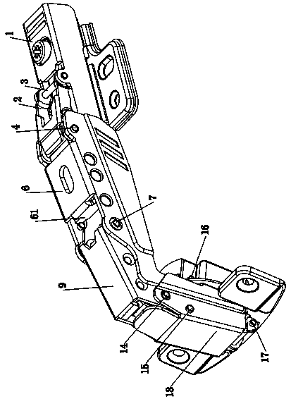
The invention relates to a large-angle door hinge. The large-angle door hinge is characterized by comprising a main body, outer rocking and inner rocking arms, a first pin shaft to a ninth pin shaft, a damper, a connecting arm, a crank, a spring base, a spring, a swing arm and a hinge cup; the outer rocking arm is connected with the main body and the connecting arm through the first and second pin shafts; a positioning convex block is arranged on the outer rocking arm; a chute is formed in the connecting arm; a slide block and an arc recess are arranged on the damper; the slide block is arranged in the chute; a piston rod of the damper is arranged on the connecting arm; the positioning convex block is positioned in the arc recess; the crank is connected with the main body through the fourth pin shaft; the crank is connected with the connecting arm and the spring base through the third pin shaft; the spring is arranged in the spring base; the spring base is connected with the crank through the fifth pin shaft; the swing arm is connected with the crank and the inner rocking arm through the sixth pin shaft; the inner rocking arm is connected with the swing arm through the seventh pin shaft; the inner rocking arm is connected with the hinge cup through the ninth pin shaft; and the hinge cup is connected with the connecting arm through the eighty pin shaft. The large-angle door hinge has the advantages of compact structure, stable buffer force and high precision.

Description

technical field [0001] The invention relates to a large-angle door hinge. Background technique [0002] At present, the existing large-angle door hinge includes an inner rocker arm, a hinge cup fixed on the door panel, a crank, a return spring, a spring seat, a connecting arm, a body installed on a frame, and an outer rocker arm, wherein the inner rocker One end of the arm is rotatably connected to the hinge cup through the first pin shaft, and the other end is rotatably connected to one end of the crank through the third pin shaft; one end of the return spring is located in the mounting hole of the spring seat, and the other end extends out of the mounting hole; One end of the spring seat is provided with two elongated holes extending outwards, the middle part of the crank, the middle part of the connecting arm and the spring seat are connected through the rotation of the fourth pin, and the fourth pin passes through the two elongated holes and is connected with the spring ...

Claims


Application Information

Patent Timeline
Patent Type & Authority Patents(China)
IPC IPC(8): E05D3/06
CPCE05D3/06
Inventor 梁业林
Owner FOSHAN TIANSI HARDWARE CO LTD
Learn More