Power control method of electromagnetic heating device and cooking device
An electromagnetic heating device and power control technology, which is applied to the power control of electromagnetic heating devices and the field of cooking devices with electromagnetic heating, can solve the problems of power tube breakdown, high power tube back pressure, and long PWM signal turn-on time. The effect of reducing the discharge back pressure value, shortening the charging and discharging time, and improving the power range
- Summary
- Abstract
- Description
- Claims
- Application Information
AI Technical Summary
Problems solved by technology
Method used
Image
Examples
Embodiment approach 1
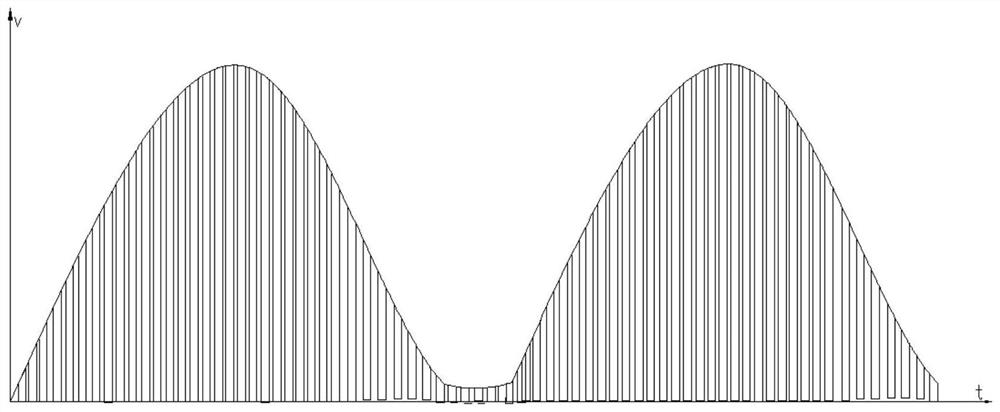
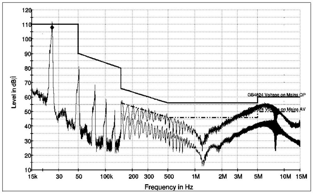
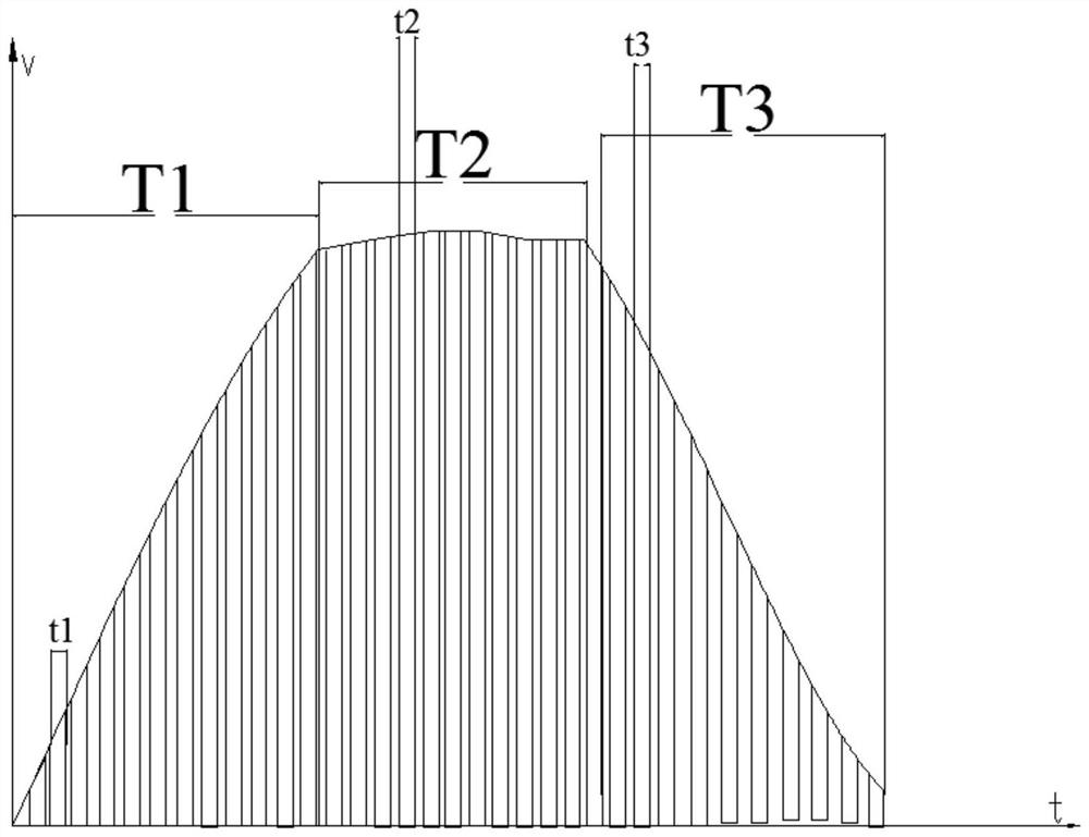
[0045] see Figure 5 , Figure 6 As shown, the power control method of an electromagnetic heating device of the present invention, the electromagnetic heating device includes a coil, a power tube, an oscillating capacitor connected in parallel with the coil, a main control chip with a PWM signal output port, and a drive power tube to work The drive circuit, the PWM signal output port of the main control chip is connected to the drive circuit. When the power tube is in the working state, a voltage envelope is formed. This voltage envelope can be tested with an oscilloscope for easy observation.
[0046] The main improvement of the control method of the present invention is that the main control chip divides the voltage envelope into three driving stages:
[0047] The first driving stage: the main control chip controls the conduction time of the PWM signal output to be t1;
[0048] The second driving stage: the main control chip controls the conduction time of the PWM signal...
Embodiment approach 2
[0056] see Figure 7 , Figure 8 As shown, the second embodiment of the power control method of an electromagnetic heating device in the present invention differs from the first embodiment in that: the electromagnetic heating device also includes a zero-crossing detection circuit, and the main control chip is based on the zero-crossing detection circuit After obtaining the zero-crossing signal, enter the first driving stage.
[0057] In this embodiment, through the detection of the zero-crossing signal, the heating time of each stage can be accurately controlled, that is, the starting time is accurate, which effectively ensures the effective execution of each driving stage.
[0058] Other structures and beneficial effects of this embodiment are consistent with Embodiment 1 and will not be repeated here.
Embodiment approach 3
[0060] see Figure 9 , Figure 10 As shown, the third embodiment of the power control method of the electromagnetic heating device of the present invention is different from the first embodiment in that: the electromagnetic heating device also includes a back pressure detection circuit of the power tube, and the pre-set value in the main control chip Set the back-voltage limit value, if the back-voltage value acquired by the back-voltage detection circuit reaches the back-voltage limit value V0, the voltage envelope enters the second drive stage from the first driving stage, wherein the back-voltage limit value V0 is above 1 kV. Specifically, the back-voltage limit value in this embodiment is between 1 kV and 1.3 kV, and the optimal value is 1.1 kV.
[0061] In this embodiment, the back pressure limit is used as the switching basis of the driving stage, instead of the time base of Embodiment 1, so that no matter what heating state the electromagnetic heating device is in, as ...
PUM
 Abstract
Description
Claims
Application Information
 - R&D
- Intellectual Property
- Life Sciences
- Materials
- Tech Scout
- Unparalleled Data Quality
- Higher Quality Content
- 60% Fewer Hallucinations
Browse by: Latest US Patents, China's latest patents, Technical Efficacy Thesaurus, Application Domain, Technology Topic, Popular Technical Reports.
© 2025 PatSnap. All rights reserved.Legal|Privacy policy|Modern Slavery Act Transparency Statement|Sitemap|About US| Contact US: help@patsnap.com


