
Air-cooled battery pack with high heat dissipation efficiency

A high heat dissipation, battery pack technology, applied in secondary batteries, battery pack components, circuits, etc., can solve the problem of the large connection span between the module and the module waterway, the difficulty of ensuring the temperature consistency of the module, and the inconvenience of maintenance and repair. problems, to avoid short-circuit risks, simple structure, and reduce maintenance costs.

Active Publication Date: 2017-10-20
SYST ELECTRONICS TECH ZHENJIANG CO LTD
View PDF5 Cites 7 Cited by
  • Summary
  • Abstract
  • Description
  • Claims
  • Application Information

AI Technical Summary

Problems solved by technology

However, the disadvantages and deficiencies of air cooling are: poor heat dissipation effect, high requirements for air duct design and structural arrangement, and difficulty in ensuring module temperature consistency, especially for batteries near the air outlet, heat will accumulate, although maintenance Simple, but not ideal cooling effect
However, the disadvantages and deficiencies of liquid cooling are: ideal heat dissipation effect, complex waterway design, especially the intricate waterway connection between modules in the battery box, and different fixing methods for different modules in the battery box. If the system is running at a lower level, the waterway connection between the modules has a large span, and the probability of liquid leakage also increases at the same time.
If some parts of the heat dissipation system are damaged during long-term use, the overall heat dissipation system needs to be disassembled, which is extremely inconvenient for maintenance

Method used

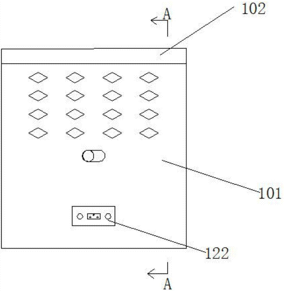
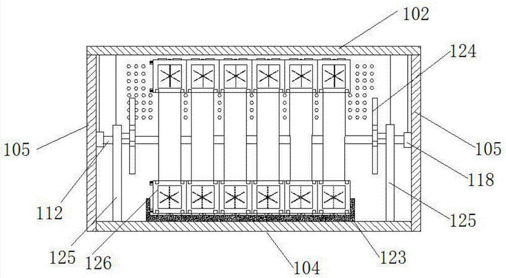
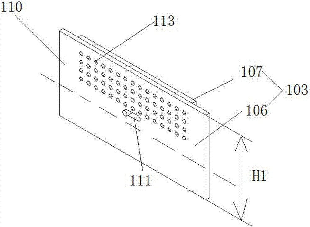

Image

  • Air-cooled battery pack with high heat dissipation efficiency
  • Air-cooled battery pack with high heat dissipation efficiency
  • Air-cooled battery pack with high heat dissipation efficiency

Examples


Embodiment Construction

[0041] The present invention will be further described below in conjunction with the accompanying drawings and specific embodiments.

[0042] In the description of the present invention, it should be noted that the terms "center", "upper", "lower", "left", "right", "vertical", "horizontal", "inner", "outer" etc. The indicated orientation or positional relationship is based on the orientation or positional relationship shown in the drawings, and is only for the convenience of describing the present invention and simplifying the description, rather than indicating or implying that the referred device or element must have a specific orientation, or in a specific orientation. construction and operation, therefore, should not be construed as limiting the invention. In addition, the terms "first", "second", and "third" are used for descriptive purposes only, and should not be construed as indicating or implying relative importance.

[0043] An air-cooled battery pack with high heat...


PUM


Abstract

The invention provides an air-cooled battery pack with high heat dissipation efficiency. A second side plate can be moved along a first mounting plate so that the opening and plugging of a first heat emission hole on the first side plate are realized. A second sealing plate can be moved along a second mounting plate so that the opening and plugging of a second heat emission hole on the second sealing plate are realized. The air-cooled battery pack ensures the heat dissipation of the battery pack and the tightness of the battery pack. Through arrangement of fans along four directions of a cell, cross-ventilation is improved and fast heat dissipation is realized. Multiple cell support units are flexibly connected. Pressure relief sheets are arranged. The pressure relief sheets between each two adjacent cell support units are arranged at an interval. In cell explosion, heat and pressure can be effectively released, the explosion-caused surrounding cell loss is reduced, the safety coefficients of the module, assembly and whole battery pack are improved, a battery pack maintenance cost is reduced, a contact area with the air is increased and a part of heat produced by cell work is released.

Description

technical field [0001] The invention relates to the technical field of batteries, in particular to an air-cooled battery pack with high heat dissipation efficiency. Background technique [0002] A module is composed of multiple single batteries or super capacitors connected in series and parallel, and then a battery pack with a certain voltage and capacity is formed by connecting multiple modules in series and parallel, and placed inside a sealed box to form a battery pack. During the use of the battery pack, a large amount of heat will be generated, causing the temperature of the battery pack to rise. Especially in summer, the battery pack is prone to high-temperature fire, explosion and other safety hazards. Battery pack heat dissipation technology is a big problem. Battery pack sealing requirements for safety considerations and battery pack heat dissipation are relatively contradictory issues. Most battery packs use air-cooled heat dissipation and liquid-cooled heat dissi...

Claims


Application Information

Patent Timeline
IPC IPC(8): H01M10/613H01M10/6563H01M2/10
CPCH01M10/613H01M10/6563H01M50/20Y02E60/10
Inventor 任纯麟
Owner SYST ELECTRONICS TECH ZHENJIANG CO LTD
Learn More