
Vacuum heat insulation body

一种真空隔热体、真空排气的技术,应用在通过隔热保护管道、热交换设备、制冷装置隔离等方向,能够解决难以实现实用化、连续气泡聚氨酯泡沫排气阻力大等问题

Inactive Publication Date: 2017-10-13
PANASONIC INTPROP MANAGEMENT CO LTD
View PDF6 Cites 4 Cited by
  • Summary
  • Abstract
  • Description
  • Claims
  • Application Information

AI Technical Summary

Problems solved by technology

Therefore, the exhaust resistance of the entire continuous-cell urethane foam is very large. In order to vacuumize the space for heat insulation of large containers such as refrigerator doors and casings, it takes a large amount of exhaust time, ranging from several hours to several days, and it is difficult to achieve practical use. change

Method used


Image

  • Vacuum heat insulation body
  • Vacuum heat insulation body
  • Vacuum heat insulation body

Examples


Embodiment approach 1

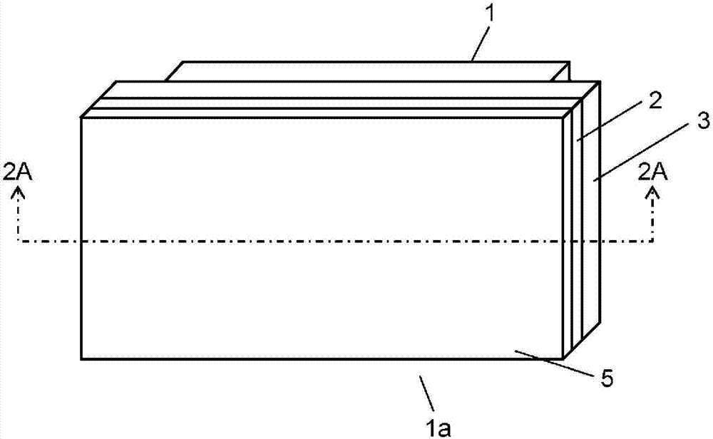
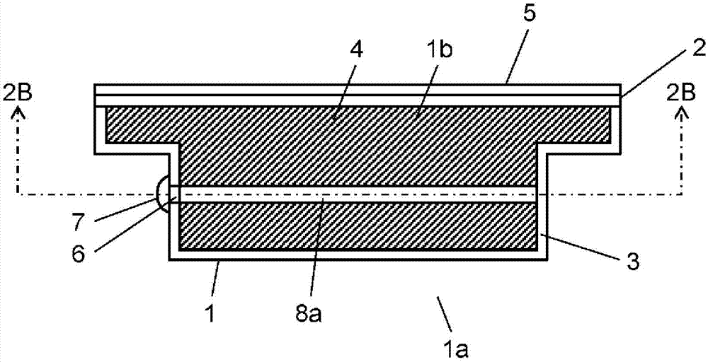
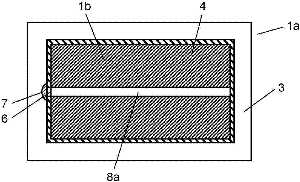
[0050] figure 1 It is a perspective view of the refrigerator door 1a including the vacuum heat insulating body (Hereinafter, a box-shaped vacuum heat insulating body is also called a vacuum heat insulating box) 1 which concerns on Embodiment 1 of this invention. Figure 2A yes figure 1 A sectional view of line 2A-2A of the refrigerator door 1a shown, Figure 2B yes Figure 2A A cross-sectional view of line 2B-2B.

[0051] Such as Figure 2A As shown, the vacuum heat insulating body 1 of this embodiment has a box shape (henceforth the vacuum heat insulating body 1 or the vacuum heat insulating box 1). Refrigerator door 1a is provided with appearance member 5 formed of glass, metal, etc., and vacuum heat insulation box 1 on the surface. The vacuum heat-insulating box 1 has an outer case 2 made of a gas-barrier material, an inner case 3 also made of a gas-barrier material, and continuous air bubbles filling a heat-insulating space 1b between the outer case 2 and the inner case...

Embodiment approach 2

[0093] The vacuum heat insulation box 1 according to Embodiment 2 of the present invention includes figure 1 The external shape of the refrigerator door 1a of the vacuum heat insulation box 1 of Embodiment 1 shown is the same.

[0094] Figure 9A It is a sectional view showing the vacuum heat insulation box 1 of this embodiment, and is figure 1 It is a sectional view of line 2A-2A of the shown refrigerator door 1a. Figure 9B yes Figure 9A Sectional view of line 9B-9B.

[0095] In this embodiment, the continuous cell urethane foam 4 is foamed in the entire inside of the vacuum heat insulating box 1 . Similar to Embodiment 1, the vacuum heat insulating box 1 of this embodiment has an outer case 2 made of a gas-barrier material, an inner case 3 similarly made of a gas-barrier material, and the outer case 2 and inner case 3 filled with The open-cell polyurethane foam 4 (core material of the vacuum heat insulation layer) is used for the heat insulation space 1b between them....


PUM


Abstract

A vacuum heat insulation body is provided with: an outer case (2); an inner case (3); an open cell urethane foam (4) filling a space for heat insulation (1b) between the outer case (2) and the inner case (3); and a vacuum discharge port (6) which is provided to the outer case (2) or the inner case (3). The open cell urethane foam (4) is provided with a through passage (8a) that penetrates the open cell urethane foam (4) from the vacuum discharge port (6). The vacuum discharge port (6) is sealed after the space for heat insulation (1b), which is filled with the open cell urethane foam (4), is vacuum-evacuated.

Description

technical field [0001] The present invention relates to vacuum heat insulating bodies used for refrigerators and the like. Background technique [0002] In recent years, as a countermeasure against global warming, which is a problem of the global environment, activities to promote energy conservation have become increasingly active. For example, in various cold and heat preservation equipment such as refrigerators and vending machines, independent cell polyurethane foam (urethane foam) is foamed and filled from the space for heat insulation between the outer box and the inner box of the heat insulation box that constitutes the main body. ) to the method of filling and forming closed-cell polyurethane foam (closed-cell polyurethane foam) on the basis of arranging vacuum insulation materials in the space for heat insulation. [0003] The vacuum heat insulating material is a material obtained by sealing a core material made of glass wool or the like under reduced pressure in a...

Claims


Application Information

Patent Timeline
Patent Type & Authority Applications(China)
IPC IPC(8): F16L59/065F25D23/06
CPCF16L59/065F25D23/06F25D23/064F25D2201/1262F25D2201/14Y10T428/231
Inventor 河原崎秀司平井刚树平野俊明北野智章
Owner PANASONIC INTPROP MANAGEMENT CO LTD
Learn More