
Automatic quantitative timed feeding cleaning device

A technology of timing feeding and cleaning device, applied in the field of animal husbandry, can solve the problems of endangering the safety of livestock or poultry, fighting for livestock or poultry, stacking together, etc., to achieve the effect of timing and quantitative feeding, and facilitating time and quantity control.

Inactive Publication Date: 2017-10-10
程建
View PDF0 Cites 8 Cited by
  • Summary
  • Abstract
  • Description
  • Claims
  • Application Information

AI Technical Summary

Problems solved by technology

In densely populated places, livestock and poultry are usually fed together. When feeding livestock or poultry, special troughs are usually used. Different troughs are selected according to the different livestock. The traditional trough only has a simple feeding structure. Food will pile up together, which will easily cause competition for livestock or poultry, which will not only endanger the safety of livestock or poultry, but also easily cause food waste during the competition
Moreover, when the breeder is feeding, it is difficult to accurately grasp the amount of feeding, so it is easy to cause food waste
And food is often polluted after livestock eats, especially when poultry eats, often jumps in the trough, makes the food in the trough polluted
The traditional trough needs to manually remove the food and residues to ensure the cleanliness of the trough, which is very inconvenient to use

Method used


Image

  • Automatic quantitative timed feeding cleaning device
  • Automatic quantitative timed feeding cleaning device
  • Automatic quantitative timed feeding cleaning device

Examples


Embodiment Construction

[0017] Below in conjunction with accompanying drawing and embodiment the present invention is further described:

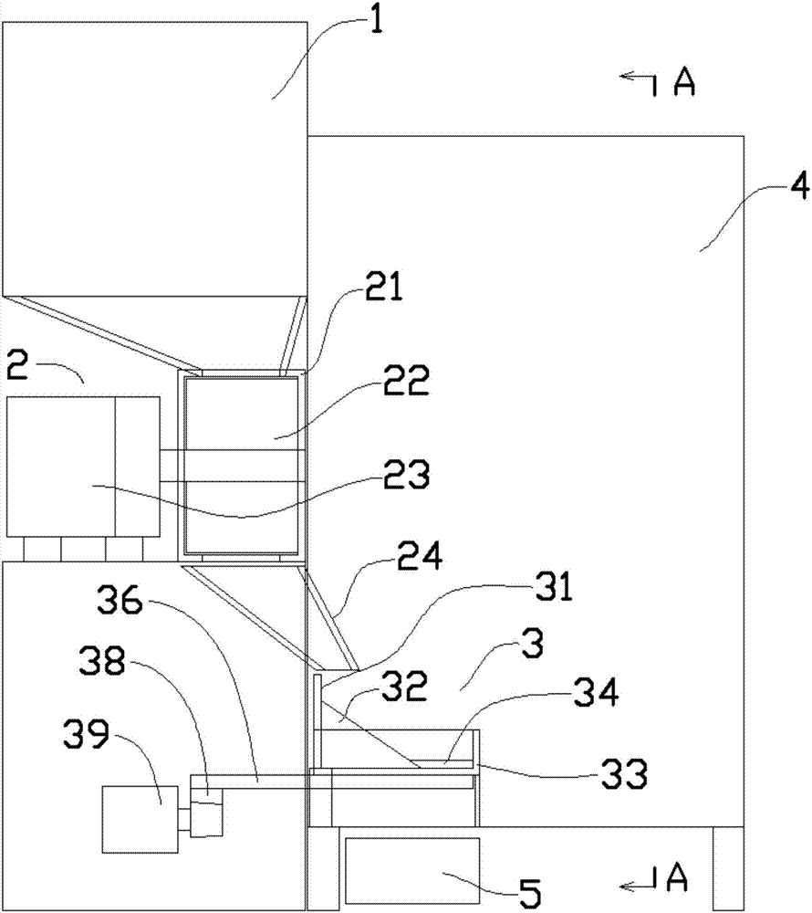
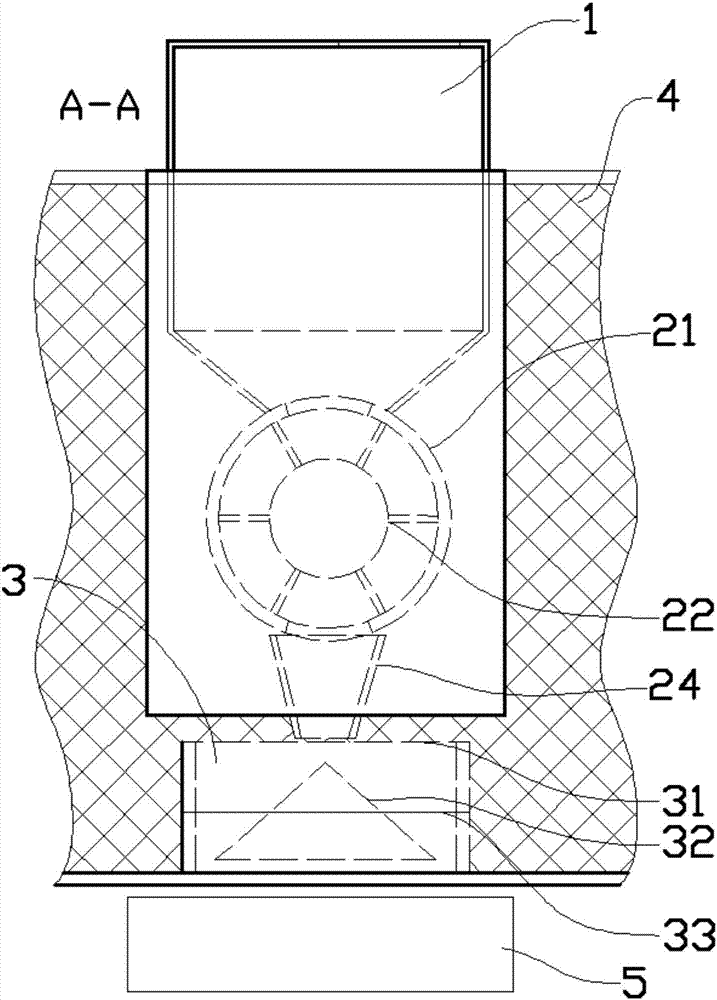
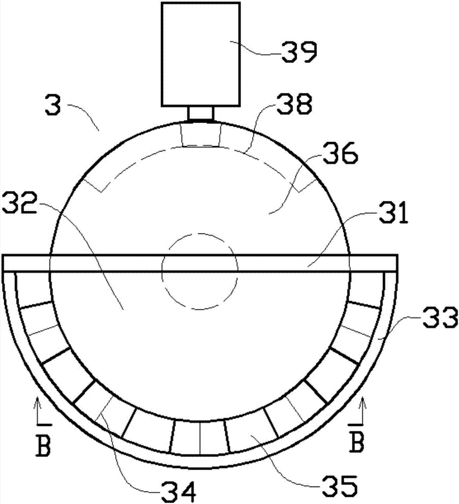
[0018] like Figure 1 to Figure 5 As shown in the embodiment, the automatic quantitative and timing feeding and cleaning device includes a main hopper 1, a feeder 2, and a trough 3; Cavity, the cylindrical cavity of the housing is equipped with a material distribution impeller 22, the material distribution impeller 22 includes a rotating shaft that is rotatably assembled with both ends of the cylindrical cavity, and the circumference of the rotating shaft is evenly distributed with shafts parallel to the axis of the cylindrical cavity The blade, the gap between the side of the blade away from the rotating shaft and the annular inner wall of the cylindrical cavity is less than 5mm, which can also prevent the material particles from being exposed from the gap. One side shaft end of the rotating shaft protrudes from the casing 21 and is connected to the discharge mo...


PUM


Abstract

The invention provides an automatic quantitative and timing feeding and cleaning device, which includes a main hopper, a feeder, and a food trough; the feeder includes a shell, and the cylindrical cavity of the shell is equipped with a feeder impeller. The upper part of the cylindrical cavity of the housing is connected with the lower outlet of the main hopper, and the lower part of the cylindrical cavity is connected with the upper part of the trough through the hopper. The trough is placed horizontally, and a vertical stop is designed on the rear side of the trough. The material rear plate, the front side of the material retaining rear plate is fixed with a material distribution cone, and the front part of the material distribution cone is designed with a semi-circular material retaining front plate, between the material distribution cone and the material retaining front plate They are connected by a semi-circular feeding plate. The structure of the material distribution cone allows the material flowing out from the lower part of the hopper to slide from a point to a semi-circular surface to achieve the purpose of uniform material distribution; in addition, the design of the material distributor can be controlled by controlling the discharge motor. Rotate to control the falling amount of material.

Description

Technical field [0001] The invention belongs to the technical field of animal husbandry, and in particular relates to an automatic quantitative and timing feeding and cleaning device. Background technique [0002] Animal husbandry refers to the use of livestock, poultry and other animals that have been artificially raised and domesticated by humans, or the physiological functions of wild animals such as deer, musk deer, fox, mink, otter, quail, etc., through artificial breeding and breeding, so that they can combine pasture and grass. Plants such as feed can be transformed into animal energy to obtain livestock products such as meat, eggs, milk, wool, cashmere, hides, silk and medicinal materials. Depending on the size of the livestock and the place where they are raised, the raised livestock adopt different feeding methods. In densely populated places, livestock and poultry are usually fed intensively. When feeding livestock or poultry, special troughs are usually used. Di...

Claims


Application Information

Patent Timeline
IPC IPC(8): A01K39/012A01K5/02
CPCA01K39/012A01K5/0225A01K5/0283A01K5/0291
Inventor 程建
Owner 程建
Learn More