High-speed circuit breaking array for breaking a current path in a switching device

A high-speed circuit breaking and switching equipment technology, applied to the components, circuits, relays, etc. of the protection switch, can solve the problems that the contacts cannot be permanently opened

Active Publication Date: 2017-09-26
EATON INTELLIGENT POWER LIMITED
View PDF8 Cites 5 Cited by
  • Summary
  • Abstract
  • Description
  • Claims
  • Application Information

AI Technical Summary

Problems solved by technology

Once the contacts are opened, this current decreases rapidly again, and therefore a high-speed circuit breaker cannot ensure permanent opening of the pair of contacts

Method used


Image

  • High-speed circuit breaking array for breaking a current path in a switching device
  • High-speed circuit breaking array for breaking a current path in a switching device
  • High-speed circuit breaking array for breaking a current path in a switching device

Examples


Embodiment Construction

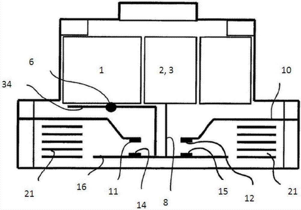
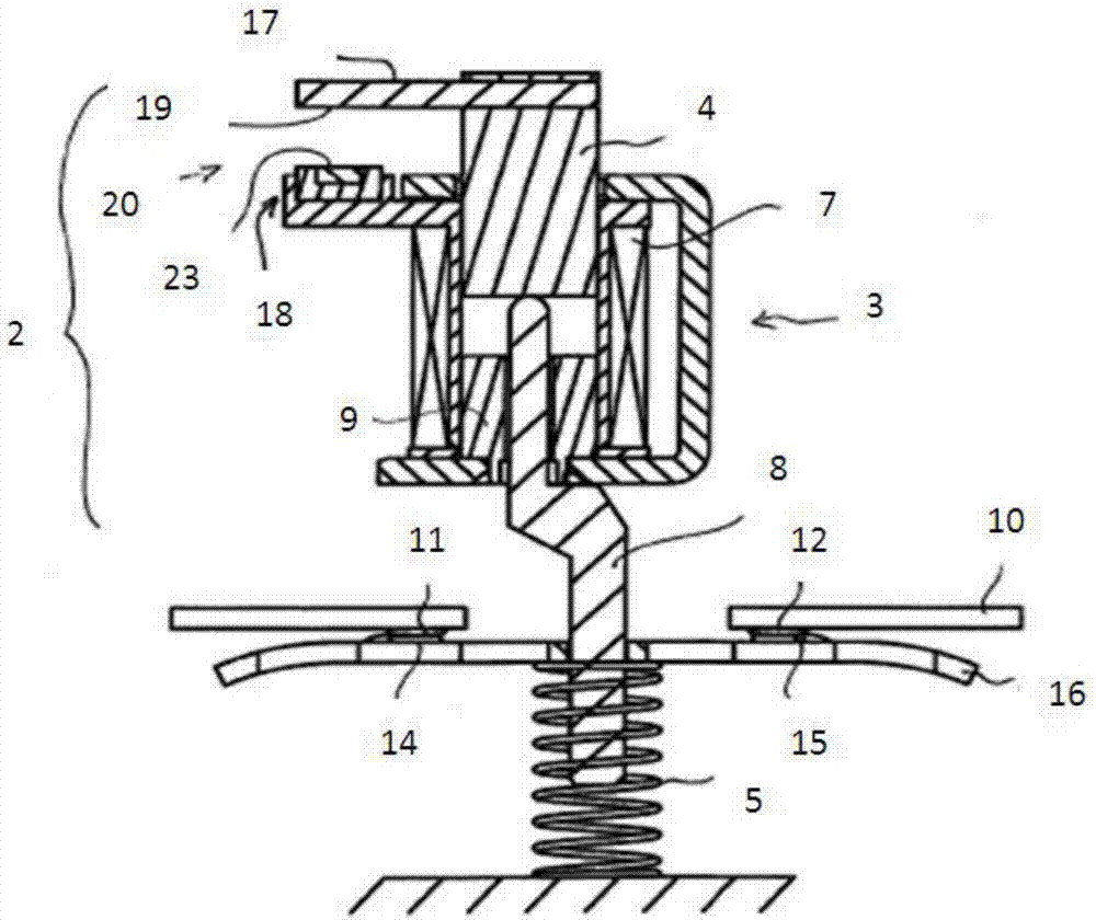
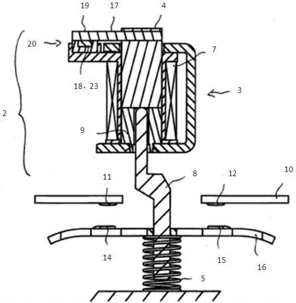
[0032] figure 1 is a simplified schematic diagram of a switchgear in which a high-speed circuit breaker device 2 and a driver 1 for switching during operation are arranged in one common housing. The switchgear for switching on or off the current passing through the current path 10 comprises two stationary contacts 11, 12 in order to switch on or off the current, said two static contacts 11, 12 being connected with a moving contact holder 16 The two moving contacts 14, 15 on the upper cooperate with each other to close and cut off the current path 10. The electromagnetic drive 1 is used to move the movable contact carrier 16 between a closed position (not shown) and an open position (shown in the figures) during operation, wherein in the closed position, the pairs of contacts 11, 14 and 12, 15 is closed. The high-speed circuit breaker device 2 for interrupting the current path 10 in the event of a short circuit or overload is also only shown schematically here. The specific ...


PUM


Abstract

The invention relates to a high-speed circuit breaking array for breaking a current path in a switching device in the event of a short circuit or overload, having a drive for moving a drive armature from a standby position to a trigger position, wherein the movement of the drive armature is designed to act on at least one movable contact of the switching device in such a way that the current path is broken using a holding device. The invention also relates to a switching device having a contact system comprising at least one fixed contact and at least one movable contact, wherein in order to make and break a current path the movable contact can be reversibly moved in relation to the fixed contact between a make position and a break position by means of a drive for the purpose of functional switching, and having a high-speed circuit breaking array of this type.

Description

technical field [0001] The invention relates to a high-speed circuit breaker device for breaking a current path in a switchgear in the event of a short circuit or overload, comprising: a drive for moving a drive armature from a stand-by position to a trip position, said drive armature being intended to acting on at least one moving contact of the switchgear so that the current path is cut off; holding means for holding said drive armature in a tripped position. The invention also relates to a switchgear comprising a contact system consisting of at least one stationary contact and at least one moving contact, by means of a drive for switching during operation, said moving contact relative to the The stationary contacts reversibly move between a closed position and an open position to close and break a current path. Background technique [0002] For example, switching devices of this type including corresponding electromagnetic drives are used in motor starters. These switch...

Claims


Application Information

Patent Timeline
Patent Type & Authority Applications(China)
IPC IPC(8): H01H50/32
CPCH01H50/32H01H2050/325H01H71/32H01H71/321H01H71/322
Inventor V·朗
Owner EATON INTELLIGENT POWER LIMITED
Why Eureka
Try Eureka