Mechanical interlock assembly for disconnector and earthing switch

一种接地开关、机械互锁的技术,应用在接地开关、空气开关零部件、电开关等方向,能够解决难以安装和维护、难安装和维护、不那么可靠等问题,达到安装和维护简单、结构简单、提高可靠性的效果

Active Publication Date: 2017-09-26
HITACHI ENERGY LTD
View PDF6 Cites 5 Cited by
  • Summary
  • Abstract
  • Description
  • Claims
  • Application Information

AI Technical Summary

Problems solved by technology

Not only are these structures very complex and expensive, they are also very difficult to install and maintain
With existing interlocks between the disconnector and the associated earthing switch (separated by a long distance from the disconnector), the interlock is more complex and less reliable, and very difficult to install and maintain

Method used


Image

  • Mechanical interlock assembly for disconnector and earthing switch
  • Mechanical interlock assembly for disconnector and earthing switch
  • Mechanical interlock assembly for disconnector and earthing switch

Examples


Embodiment Construction

[0042] Hereinafter, the mechanism and spirit of the present disclosure will be described with reference to exemplary embodiments. It should be understood that these embodiments are provided only to facilitate those skilled in the art to understand and implement the present disclosure, and are not intended to limit the scope of the present disclosure in any way.

[0043] Various embodiments of the present disclosure will be described in detail herein in an exemplary manner by referring to the accompanying drawings.

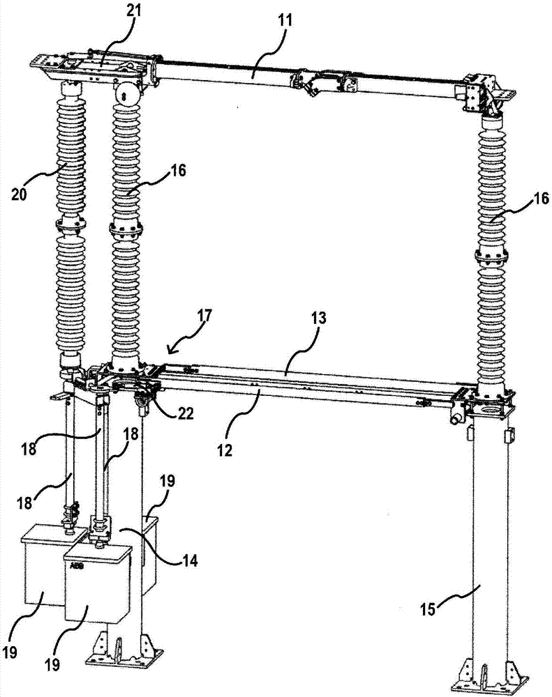
[0044] figure 1 Exemplary switching devices are illustrated. The switchgear comprises an isolating switch 11 , a first associated earthing switch 12 and a second associated earthing switch 13 . The isolating switch 11 includes movable contacts and fixed contacts. The movable contact is pivotally supported on the first mounting post 14 and is insulated from the first mounting post 14 by an insulating member 16 (eg, a ceramic insulating member). The fixed contact...


PUM


Abstract

A mechanical interlock assembly for a disconnector and an earthing switch is provided. It comprises: a main interlock disc (172) configured to actuate a movable contact of a disconnector (11), and at least one earthing switch interlock disc (173, 173') configured to actuate respective movable contact of at least one earthing switch (12, 13) respectively. The main interlock disc (172) is provided with at least one first groove (1721), and each of the at least one earthing switch interlock disc (173, 173') is provided with a third groove (1731), and it is provided with a movable interlock pin (174) between the main interlock disc (172) and each earthing switch interlock disc (173, 173') respectively. This interlock assembly can interlock the disconnector and the at least one earthing switch, and has the advantages of a simple structure, low cost and flexibility for different arrangements. A further mechanical interlock assembly is also provided to interlock another disconnector and one of the above at least one earthing switch.

Description

technical field [0001] Embodiments of the present disclosure relate to the field of mechanical interlock assemblies for disconnectors and earthing switches, and to a switchgear having such a mechanical interlock assembly. Background technique [0002] An isolating switch is a mechanical switch used to isolate an electrical device from a power line. It is usually used in a high-voltage environment to form a visible disconnection point to ensure reliable isolation of the electrical device from the power line so that the electrical device can be safely operated without a load. operation or maintenance. Typically, at least one grounding switch is used with an isolating switch to connect the isolated electrical device to ground so that residual capacitive or inductive currents on the isolated electrical device can be eliminated and the isolated electrical device can be operated or maintained more safely electrical installations. [0003] It is a basic requirement that the isola...

Claims


Application Information

Patent Timeline
Patent Type & Authority Applications(China)
IPC IPC(8): H01H9/26
CPCH01H9/24H01H31/003H01H31/08H01H31/10H01H31/28H01H33/42H01H9/26H01H3/46H01H31/32
Inventor 陈锐袁志鹏刘璿颜家全
Owner HITACHI ENERGY LTD
Why Eureka
Try Eureka