
Eyepiece Optical System

An optical system and eyepiece technology, applied in the field of optical systems, can solve the problems of narrow vision, serious aberrations, low resolution, etc., and achieve the effect of shortening the length of the system and overcoming aberrations

Active Publication Date: 2020-03-17
GENIUS ELECTRONICS OPTICAL XIAMEN
View PDF5 Cites 0 Cited by
  • Summary
  • Abstract
  • Description
  • Claims
  • Application Information

AI Technical Summary

Problems solved by technology

[0003] The half eye viewing angle of the existing eyepiece optical system is small, which makes the observer feel that the vision is narrow, the resolution is low, and the aberration is so serious that the display screen needs to be compensated first. Therefore, how to increase the half eye viewing angle and enhance the image quality The system is a problem that needs improvement

Method used


Image

  • Eyepiece Optical System
  • Eyepiece Optical System
  • Eyepiece Optical System

Examples


Embodiment Construction

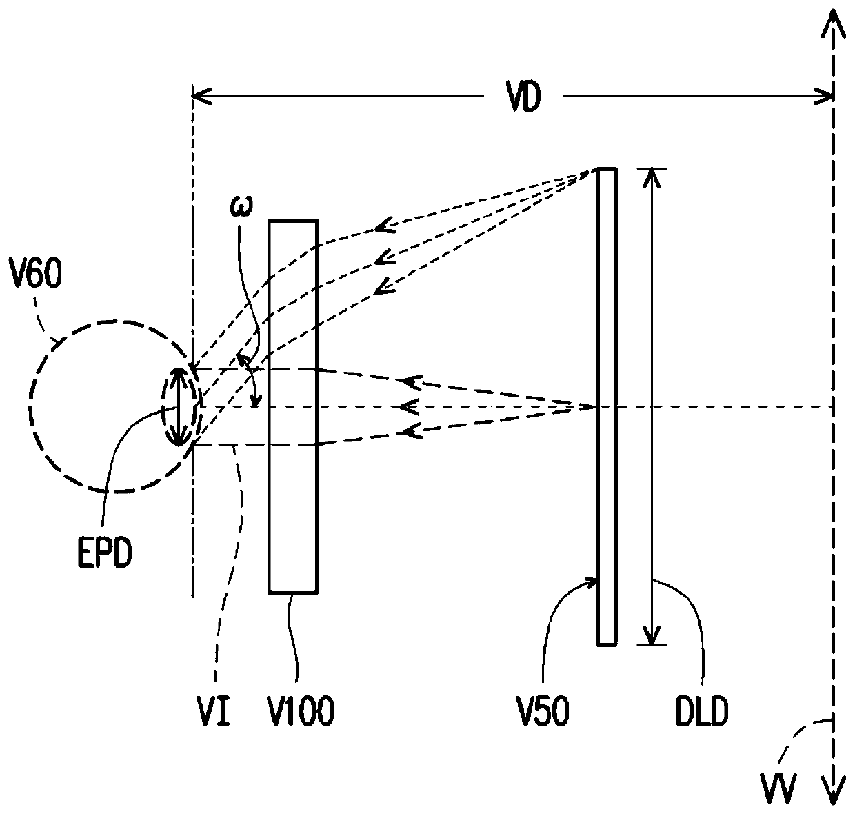
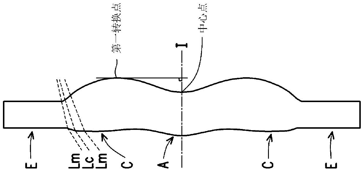
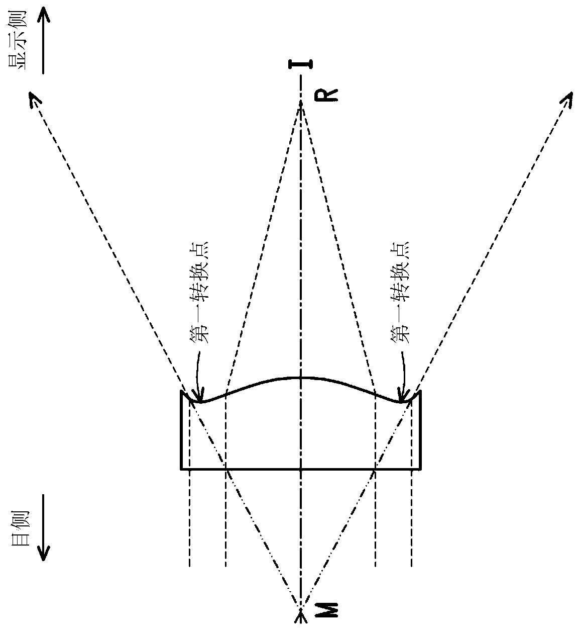
[0092] For a more complete understanding of the description and its advantages, the present invention is provided with drawings. These drawings are part of the disclosure of the present invention, which are mainly used to illustrate the embodiments, and can be used in conjunction with the relevant descriptions in the manual to explain the operating principles of the embodiments. With reference to these contents, those skilled in the art should understand other possible implementations and advantages of the present invention. Components in the figures are not drawn to scale, and similar component symbols are generally used to denote similar components.

[0093] Explanation of symbols in the accompanying drawings:

[0094]10. V100: eyepiece optical system; 100, V50: display screen; 2: pupil; 3: first lens; 31, 41, 51: eye side; 511, 513, 521, 523: convex surface; 312, 314, 412, 414, 422, 424, 512, 514, 522, 524: concave surface; 32, 42, 52: display side; 4: second lens; 425 ,...


PUM


Abstract

The invention discloses an eyepiece optical system, which is used for imaging light entering the observer's eyes from a display screen through the eyepiece optical system for imaging. The direction facing the eyes is the eye side, and the direction facing the display screen is the display side. The eyepiece optical system sequentially includes a first lens, a second lens and a third lens along an optical axis from the eye side to the display side, and each of the first lens, the second lens and the third lens includes an eye side and a display side. The second lens has positive refractive power, and the display side of the second lens has a concave portion located in the vicinity of the optical axis.

Description

technical field [0001] The invention relates to the field of optical systems, in particular to an eyepiece optical system. Background technique [0002] Virtual reality (Virtual Reality, VR) is to use computer technology to simulate a three-dimensional virtual world, providing users with visual, auditory and other sensory simulations, allowing users to feel personally on the scene. At present, existing VR devices are mainly based on visual experience. The parallax of human eyes is simulated by splitting images with slightly different viewing angles corresponding to the left and right eyes to achieve stereoscopic vision. In order to reduce the size of the virtual reality device and allow users to obtain a magnified visual experience through a smaller display screen, the eyepiece optical system with magnification function has become one of the subjects of VR research and development. [0003] The half eye viewing angle of the existing eyepiece optical system is small, which ...

Claims


Application Information

Patent Timeline
Patent Type & Authority Patents(China)
IPC IPC(8): G02B25/00
CPCG02B25/001
Inventor 马修·博恩
Owner GENIUS ELECTRONICS OPTICAL XIAMEN
Learn More