Re-conveying device in carbon fibre laying head

A laying head and carbon fiber technology, which is applied in the field of carbon fiber laying equipment, can solve the problems of complex and huge re-feeding mechanism, shutdown failure, and many motor transmission structures, and achieve the effect of strong scalability and space saving

Active Publication Date: 2017-09-22
WUHAN UNIV OF TECH
View PDF5 Cites 3 Cited by
  • Summary
  • Abstract
  • Description
  • Claims
  • Application Information

AI Technical Summary

Problems solved by technology

[0003] At present, most of the research on the placement head only designs the re-feed mechanism for one or two tows, and the speed of the re-feed driving wheel is provided by a motor, so the speed of each belt is the same. When increasing the number of tows and laying tows of different lengths at the same time, it is impossible to accurately control the speed and length of each tow re-feeding, although there are very few re-feeding mechanisms that use multiple motors to transport multiple tows at the same time. However, due to too many motors and transmission structures, the re-feeding mechanism is too complex and large, and there is no certain scalability, and the width of the prepreg yarns currently used is generally 1 / 8in (3.17mm), 1 / 4in (6.35mm) and the like. When re-transmitting, if the spacing is small, it is easy to deviate and entangle and cause downtime. If the spacing is large, the size of the equipment will be increased.

Method used


Image

  • Re-conveying device in carbon fibre laying head
  • Re-conveying device in carbon fibre laying head
  • Re-conveying device in carbon fibre laying head

Examples


Embodiment Construction

[0023] The present invention will be further described below in conjunction with the accompanying drawings and embodiments.

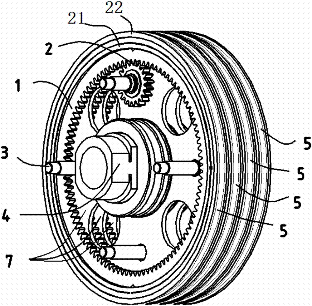
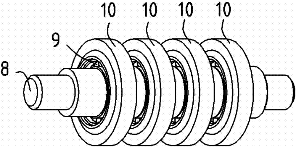
[0024] Such as Figure 4 As shown, a re-feeding device in a carbon fiber laying head includes a fixed shaft 4 and four parallel driving wheels 6 that are sleeved on the fixed shaft 4 (in this embodiment, four driving wheels 6 are used, but in fact there is no Not limited to four, can be reduced or expanded according to the actual situation), the driving wheel 6 includes an internal meshing ring gear 1 and a gear 2, and both sides of the ring gear 1 are embedded with bearings 21, and the bearings 21 are sleeved on the support disc 7, The support disc 7 is installed on the fixed shaft 4, and the gear shafts 3 of all the gears 2 pass through the support disc 7 and are connected to the respective corresponding motors 20, and all the motors 20 are concentrated at one end of the fixed shaft 4 (in practical applications, when the When needing to re-send a lot...


PUM


Abstract

The invention relates to a re-conveying device in a carbon fibre laying head. The re-conveying device comprises a fixed shaft and a plurality of drive wheels sleeving the fixed shaft in parallel, wherein each drive wheel comprises a gear ring and a gear which are internally engaged, bearings are embedded in the two side surfaces of each gear ring, the bearings sleeve a support disc, and the support disc is installed on the fixed shaft; gear shafts of all the gears all penetrate through the support disc and are connected with the respective corresponding motors; all the motors are concentrated at one end of the fixed shaft or distributed at the two ends of the fixed shaft; a groove is formed in the outer side of each gear ring or a conveying ring with a groove fixedly sleeves the outer side of the gear ring; and press rolls in one-to-one correspondence with the grooves are arranged above the drive gears. The device realizes simultaneous laying for carbon fibre tapes at different conveying speeds. The device avoids deflection and intertwining of the carbon fibre tapes, and is high in expansibility and compact in structure.

Description

technical field [0001] The invention belongs to the field of carbon fiber laying equipment, in particular to a refeeding device in a carbon fiber laying head. Background technique [0002] The carbon fiber laying process is to unwind several or dozens of prepreg yarns (or narrow tapes) from their respective reels, and transport them to the laying head through the prepreg yarn conveying system, and pass through the force measuring mechanism in the laying head , clamping mechanism, re-feeding mechanism, shearing mechanism, etc. send the tow to the laying nozzle, and then lay the carbon fiber on the surface of the workpiece through the pressure roller. The mechanism cuts the specified length of fiber or cuts one or several yarns from the laid fiber tape. After the cutting is completed, the end of the cut fiber must be cut off in order to continue the laying action. The starting end is re-transported to the laying nozzle, so the re-feed mechanism in the laying head is very impo...

Claims


Application Information

Patent Timeline
Patent Type & Authority Applications(China)
IPC IPC(8): B29C70/30B29C31/04B29C70/54
CPCB29C31/04B29C70/30B29C70/54
Inventor 田会方余江江吴迎峰黄敏陈培
Owner WUHAN UNIV OF TECH
Why Eureka
Try Eureka