Secondary core pulling mechanism for injection molding die with honeycomb-shaped side face vertical plates

An injection mold and secondary core-pulling technology, which is applied in the field of injection molds, can solve the problems of adding side core-pulling sliders, easy deformation, breakage, etc.

Pending Publication Date: 2017-09-22
滨海模塑集团有限公司
View PDF5 Cites 4 Cited by
  • Summary
  • Abstract
  • Description
  • Claims
  • Application Information

AI Technical Summary

Problems solved by technology

[0002] In the injection mold, if the side wall of the plastic part is made of a vertical plate, and the outer wall of the vertical plate is densely covered with structures such as honeycomb grooves, round grooves, and square grooves, since more grooves will have a tightness on the side core-pulling slider. Larger, if the side core-pulling slider is used to pull the core directly from the side, it will cause the side core-pulling slider to drive the vertical plate to move together, so that the vertical plate and the main body of the plastic part will be broken, and the molding product will be scrapped. In order to overcome this Defects, in the prior art, an upwardly extending baffle is formed on the fixed plate of the side pumping cylinder, a side thimble plate is arranged on the rear side of the side core pulling slider, and a side thimble is arranged on the side thimble plate, and the side thimble passes through the side pumping The core slider cooperates with part of the honeycomb groove of the product. There is a certain gap between the side ejector plate and the side core-pulling slider. A spring is set between the side ejector plate a

Method used


Image

  • Secondary core pulling mechanism for injection molding die with honeycomb-shaped side face vertical plates
  • Secondary core pulling mechanism for injection molding die with honeycomb-shaped side face vertical plates
  • Secondary core pulling mechanism for injection molding die with honeycomb-shaped side face vertical plates

Examples


Embodiment Construction

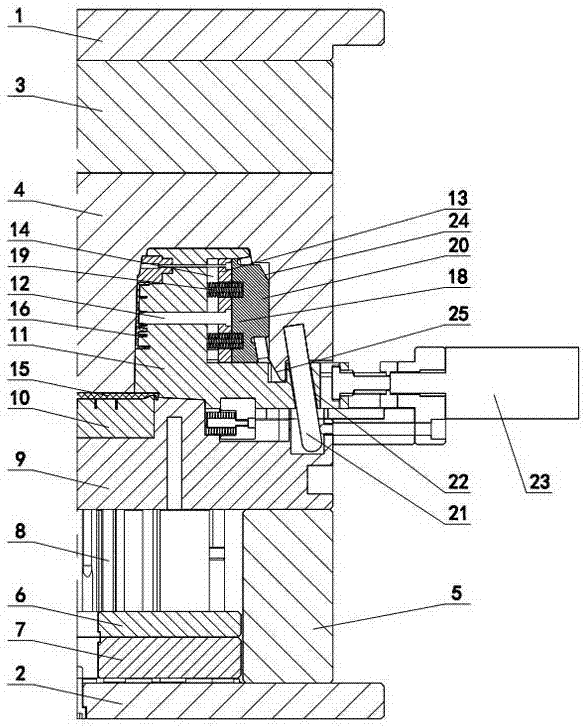
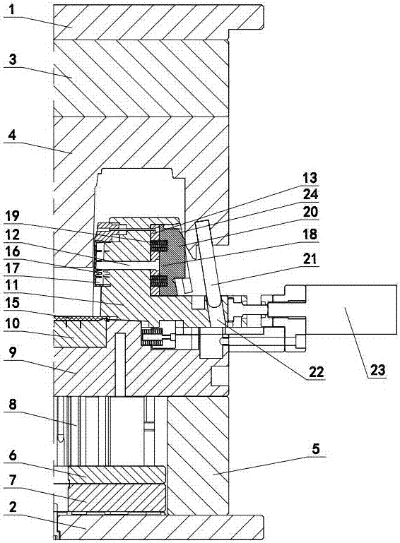
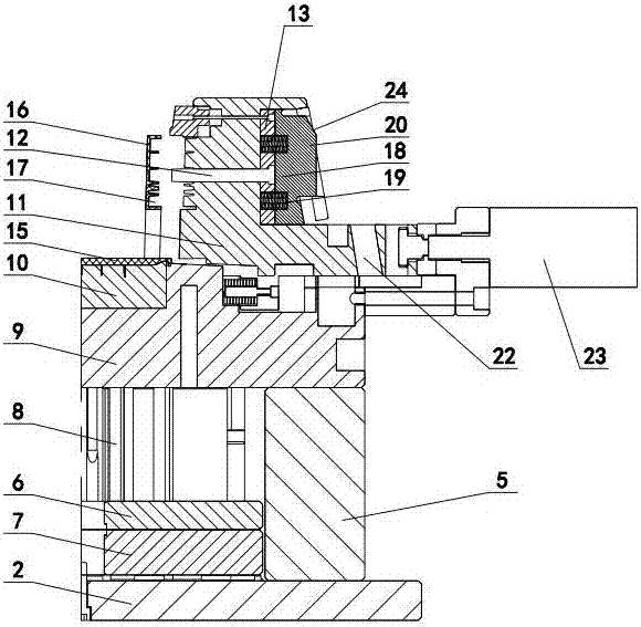
[0010] The invention relates to a secondary core-pulling mechanism for an injection mold with a honeycomb-shaped side vertical plate, such as figure 1 — image 3 As shown, it includes the upper doubler plate 1 and the lower doubler plate 2, the backing plate 3 is set under the upper doubler plate, the cavity 4 is set under the backing plate, the mold feet 5 are set on the lower doubler plate, and the lower doubler plate between the mold feet is set Upper thimble plate 6, lower thimble plate 7 and thimble 8, core 9 is set on the mold foot, core insert 10 is set in the core, side core-pulling slider 11 is set on the core, and side core-pulling slider is set in the side core-pulling slider Ejector pin 12, side ejector pin plate 13 is arranged on the outside of side core-pulling slider, there is gap 14 between side ejector pin plate and side core-pulling slider, side ejector pin connects side ejector pin plate, in core insert block, side core-pulling slider, There is an injection...


PUM


Abstract

A secondary core pulling mechanism for an injection molding die with honeycomb-shaped side face vertical plates comprises an upper compound plate and a lower compound plate. A cushion plate is arranged below the upper compound plate, and a cavity is formed below the cushion plate. The lower compound plate is provided with die feet. The part, between the die feet, of the lower compound plate is provided with an upper centre plate, a lower centre plate and a centre. Each die foot is provided with a core internally provided with a core insert, wherein the core is provided with a side core pulling sliding block internally provided with a side centre, a side centre plate is arranged on the outer side of the side core pulling sliding block, the side centre is connected with the side centre plate, a plastic piece is arranged among the core insert, the side core pulling sliding block, the side centre and the cavity, the vertical plates are manufactured on the two sides of the plastic piece, and honeycomb grooves are formed in the outer walls of the vertical plates. The secondary core pulling mechanism is characterized in that a centre bottom plate is arranged on the outer wall of each side centre plate and internally provided with a spring, wherein one side of the spring makes contact with the centre bottom plate, the other side of the spring penetrates the corresponding side centre plate to make contact with the corresponding side core pulling sliding block, a protruding block is manufactured on the outer wall of one side of the centre bottom plate, the outer wall of the protruding block makes contact with the inner wall of the cavity, an oblique guide column is arranged in the cavity, an oblique guiding hole is formed in the side core pulling sliding block, an oil cylinder is arranged on the outer wall of the core, and an oil cylinder piston rod is connected with the side core pulling sliding block.

Description

technical field [0001] The invention relates to an injection mold, in particular to a secondary core-pulling mechanism with a honeycomb-shaped side riser for the injection mold. Background technique [0002] In the injection mold, if the side wall of the plastic part is made of a vertical plate, and the outer wall of the vertical plate is densely covered with structures such as honeycomb grooves, round grooves, and square grooves, since more grooves will have a tightness on the side core-pulling slider. Larger, if the side core-pulling slider is used to pull the core directly from the side, it will cause the side core-pulling slider to drive the vertical plate to move together, so that the vertical plate and the main body of the plastic part will be broken, and the molding product will be scrapped. In order to overcome this Defects, in the prior art, an upwardly extending baffle is formed on the fixed plate of the side pumping cylinder, a side thimble plate is arranged on th...

Claims


Application Information

Patent Timeline
IPC IPC(8): B29C45/33B29C45/40
CPCB29C45/332B29C45/401B29C2045/4063
Inventor 赖小强牟能杰
Owner 滨海模塑集团有限公司
Why Eureka
Try Eureka