
Omnidirectional antenna array

An omnidirectional antenna and array technology, applied in the direction of antenna array, antenna, radiation element structure, etc., can solve the problems of high energy consumption, inability to perform wireless channel measurement, and inability to apply Ka-band or higher frequency bands, etc., to achieve omnidirectional good sex effect

Inactive Publication Date: 2017-09-19
香港城市大学深圳研究院
View PDF1 Cites 3 Cited by
  • Summary
  • Abstract
  • Description
  • Claims
  • Application Information

AI Technical Summary

Problems solved by technology

[0006] In view of this, the technical problem to be solved by the present invention is to provide an omnidirectional antenna array, which solves the problem that the omnidirectional antenna array in the prior art has a complex structure, high energy consumption, cannot be applied to the Ka band or higher frequency bands, and cannot perform Problems with wireless channel measurements

Method used


Image

  • Omnidirectional antenna array
  • Omnidirectional antenna array
  • Omnidirectional antenna array

Examples


Embodiment Construction

[0021] In order to make the purpose, technical solutions and advantages of the embodiments of the present invention clearer, the spirit of the disclosure of the present invention will be clearly described below with the accompanying drawings and detailed descriptions. Any person skilled in the art will understand the embodiments of the present invention. , when it can be changed and modified by the technology taught in the content of the present invention, it does not depart from the spirit and scope of the content of the present invention.

[0022] The exemplary embodiments and descriptions of the present invention are used to explain the present invention, but not to limit the present invention. In addition, elements / members with the same or similar numbers used in the drawings and embodiments are used to represent the same or similar parts.

[0023] As used herein, "first", "second", ... etc. do not refer to a particular sequence or order, nor are they used to limit the pre...


PUM


Abstract

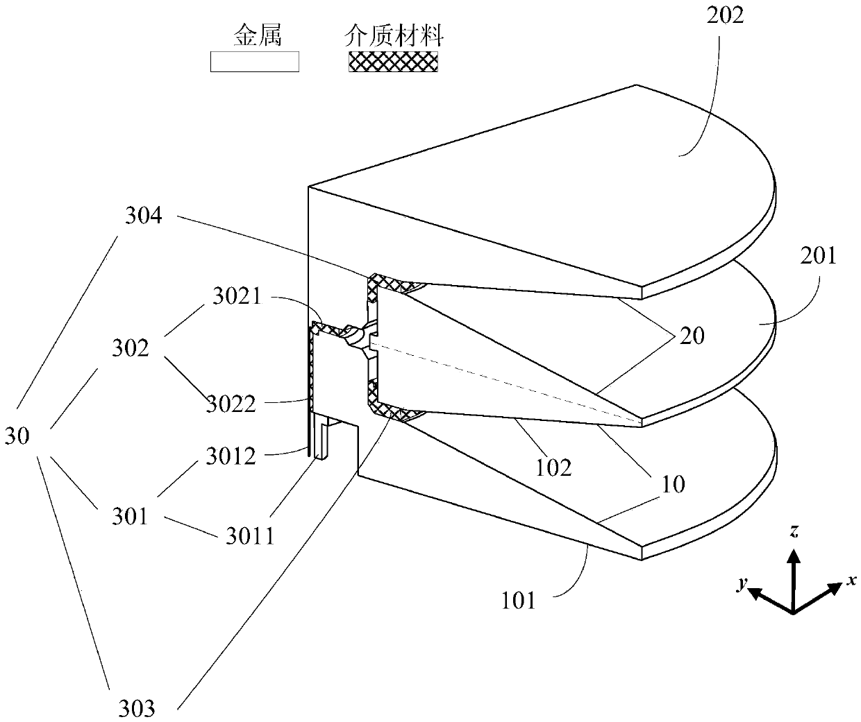
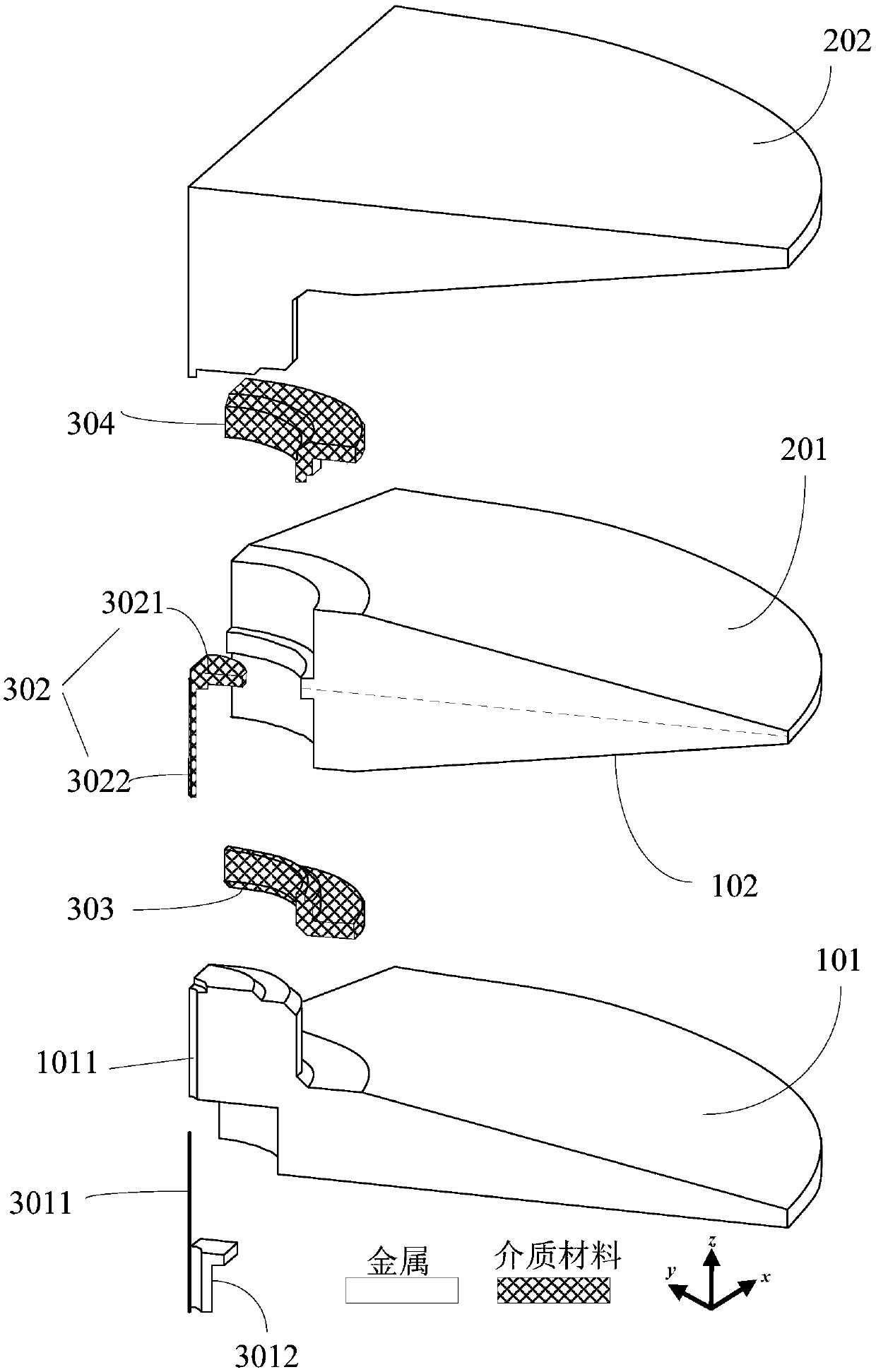
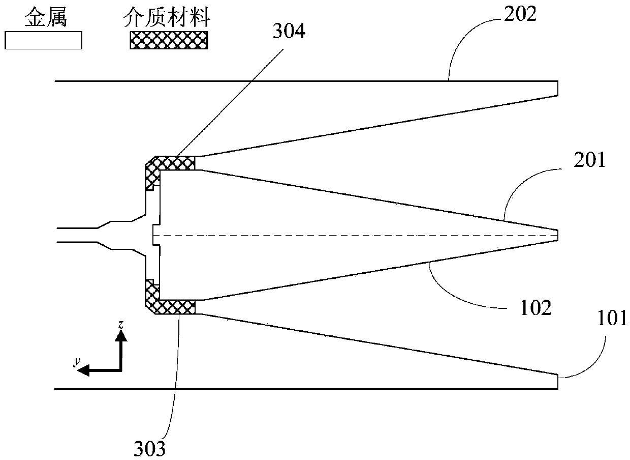
The invention provides an omnidirectional antenna array comprising a first biconical antenna unit, a second biconical antenna unit, and feed networks. The biconical antenna unit is used for receiving or transmitting a first high-frequency signal; the second biconical antenna unit stacked at the first biconical antenna unit is used for receiving or transmitting a second high-frequency signal having the same amplitude and phase as the first high-frequency signal; and the feed networks embedded in the first biconical antenna unit and the second biconical antenna unit are used for distributing high-frequency signals into a first high-frequency signal and a second high-frequency signal and transmitting the first high-frequency signal and the second high-frequency signal out or synthesizing the high-frequency signal and the second high-frequency signal into a high-frequency signal and receiving the high-frequency signal. The omnidirectional antenna array is applied to a Ka band or a higher band and a horizontal omnidirectional gain of over 10dBi is obtained.

Description

technical field [0001] The present invention relates to the technical field of antennas, in particular to an omnidirectional antenna, specifically an omnidirectional antenna array. Background technique [0002] Omnidirectional antennas show 360-degree uniform radiation on the horizontal pattern, which is commonly referred to as non-directional. Since omnidirectional antennas can cover a large range, they are widely used in the communication field. Common omnidirectional antennas include dipole antennas, monopole antennas, biconical antennas, monoconical antennas, and loop antennas. However, the low gain of existing omnidirectional antennas cannot meet certain specific requirements. In fact, there is no single omnidirectional antenna with a gain of 10 dBi in the prior art. [0003] In order to make the gain more than 10dBi, people use an omnidirectional antenna array instead of a single omnidirectional antenna. The most commonly used antenna array is a collinear antenna arr...

Claims


Application Information

Patent Timeline
Patent Type & Authority Applications(China)
IPC IPC(8): H01Q21/00H01Q1/36
CPCH01Q21/00H01Q1/36
Inventor 薛泉廖绍伟
Owner 香港城市大学深圳研究院
Learn More