Non-contact inductive switch

An inductive switch, non-contact technology, applied in the field of non-contact inductive switches, can solve problems such as false triggering and inaccurate triggering

Inactive Publication Date: 2017-09-15
MIDEA INTELLIGENT LIGHTING & CONTROLS TECH CO LTD
View PDF3 Cites 2 Cited by
  • Summary
  • Abstract
  • Description
  • Claims
  • Application Information

AI Technical Summary

Problems solved by technology

[0005] The purpose of the present invention is to overcome the problems of false triggering and inaccurate triggering in the prior art, and provide a non-contact induction switch, which can effectively avoid false triggering and is easy to use

Method used


Image

  • Non-contact inductive switch
  • Non-contact inductive switch
  • Non-contact inductive switch

Examples


Embodiment Construction

[0029] Specific embodiments of the present invention will be described in detail below in conjunction with the accompanying drawings. It should be understood that the specific embodiments described here are only used to illustrate and explain the present invention, and are not intended to limit the present invention.

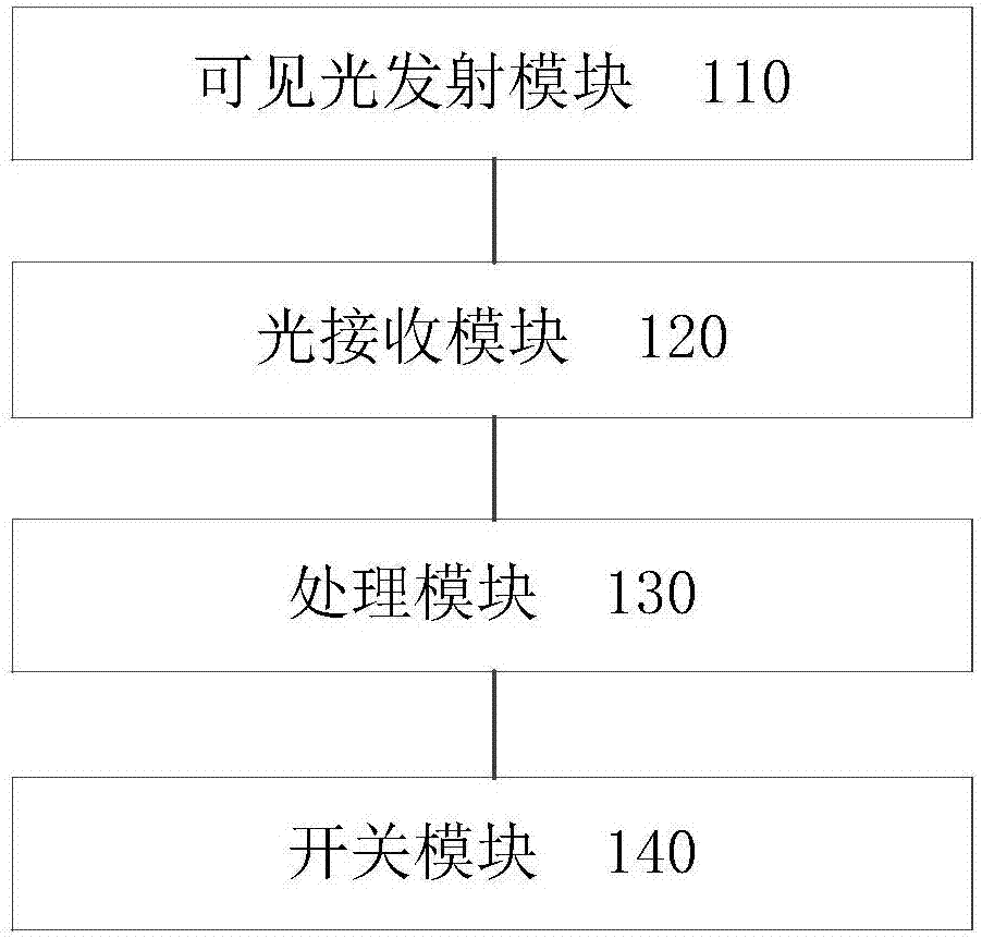
[0030] figure 1 It is a structural block diagram of a non-contact inductive switch according to an embodiment of the present invention. Such as figure 1 As shown, the sensor switch includes: a switch module 140; a visible light emitting module 110 for emitting visible light; a light receiving module 120 for receiving the visible light and processing the visible light into electrical signals; and a processing module 130 for using and controlling the switch module switch according to the electric signal. At the same time, the processing module can also control the visible light emitting module to emit visible light.

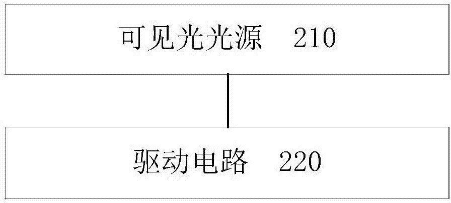
[0031] figure 2 It is a structural block...


PUM


Abstract

The invention relates to the field of switch control, and discloses a non-contact inductive switch. The inductive switch comprises a switching module, a visible light emission module for emitting visible light, a light receiving module which is used for receiving the visible light and processing the visible light into electric signals and a processing module for controlling on-off of the switching module according to the electric signals. The inductive switch can ensure the accuracy of inductive control, and the false triggering rate of the inductive switch can be greatly decreased.

Description

technical field [0001] The invention relates to the field of switch control, in particular to a non-contact induction switch. Background technique [0002] The existing non-contact induction switch is mainly based on infrared technology. The main principle is as follows: the switch device actively emits infrared rays, and the infrared rays are reflected after being blocked by external objects. The infrared receiver on the switch device detects the reflected infrared rays and converts them into electrical signals. , to control the opening and closing of the switch. Such as the infrared sensor switch in the induction faucet, the infrared sensor switch of the flush toilet, etc. [0003] The existing infrared induction switch has the disadvantage that it is easy to trigger by mistake. For example, in the washroom, people do not actually use the urinal, but just pass through the above-mentioned urinal, it is easy to trigger the flushing switch based on infrared induction, resul...

Claims


Application Information

Patent Timeline
Patent Type & Authority Applications(China)
IPC IPC(8): H03K17/94H03K17/945
CPCH03K17/941H03K17/945H03K2017/9455
Inventor 范林勇
Owner MIDEA INTELLIGENT LIGHTING & CONTROLS TECH CO LTD
Why Eureka
Try Eureka