Al technical title is built by PatSnap Al team. It summarizes the technical point description of the patent document.
A technology for positioning and locking and positioning pins, which is used in manufacturing tools, workpiece clamping devices, etc., can solve the problem of positioning pins falling easily, and the detection accuracy is not high. cost effect
Inactive Publication Date: 2019-02-19
ANHUI JIANGHUAI AUTOMOBILE GRP CORP LTD
View PDF5 Cites 0 Cited by
Summary
Abstract
Description
Claims
Application Information
AI Technical Summary
This helps you quickly interpret patents by identifying the three key elements:
Problems solved by technology
Method used
Benefits of technology
Problems solved by technology
[0006] The purpose of the present invention is to provide a positioning and locking mechanism to solve the problems that the existing positioning pins are easy to fall and the detection accuracy is not high
Method used
Image
Click on the blue label to locate the original text in one second.
Reading with bidirectional positioning of images and text.
Examples
Embodiment Construction
[0058] The technical solution of the present invention will be described in detail through the following examples. The following examples are only exemplary and can only be used to explain and illustrate the technical solution of the present invention, rather than being interpreted as a limitation to the technical solution of the present invention.
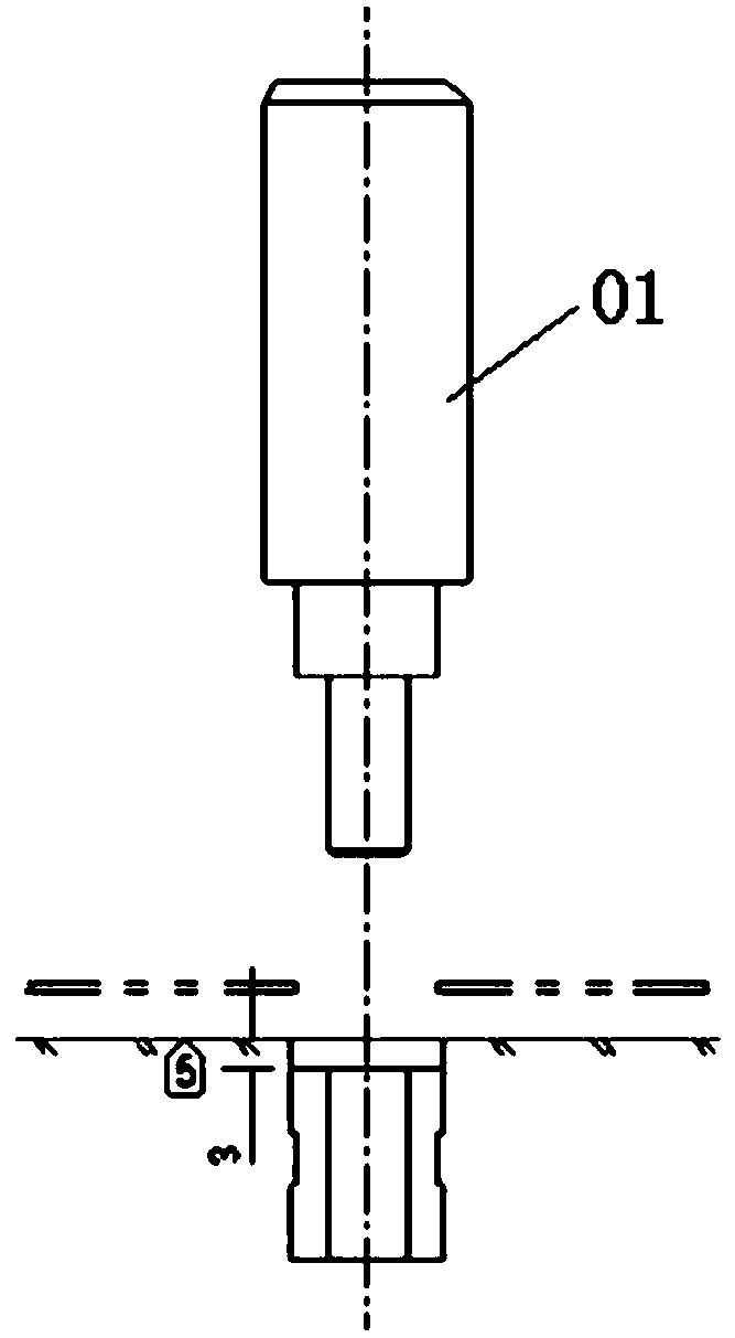
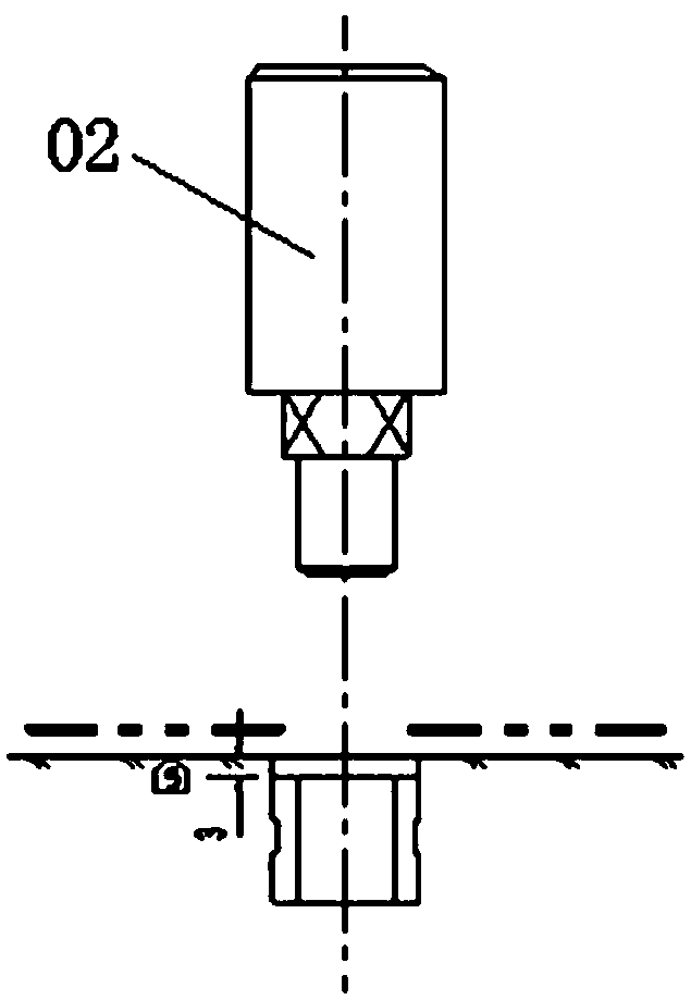
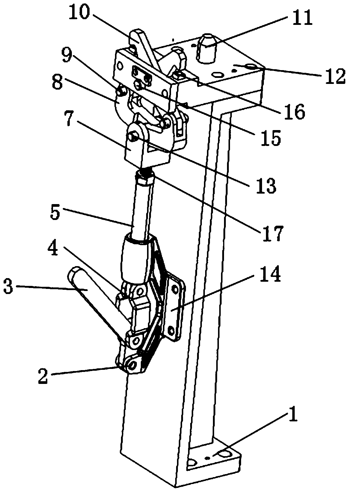
[0059] This application provides a positioning locking mechanism, such as Figure 3 to Figure 22 As shown, it includes L-shaped connecting seat 1, limit block 2, operating handle 3, U-shaped adapter block 4, linkage mechanism 5, U-shaped connecting seat 7, moving lock tongue 8, moving rotating shaft 9, and lock hook 10 , positioning pin 11, positioning bearing block 12, fixed rotating shaft 13, connecting seat 14, limiting shaft 15, S reference surface 16 and spring 17;
[0060] The positioning bearing block is fixed on the top of the L-shaped connecting seat, and the connecting seat is fixed on the side of the L-shaped connecting...
PUM
Abstract
The invention relates to a positioning and locking mechanism comprising an L-shaped connecting seat, a limiting block, an operation handle, a U-shaped adapting block, a connecting rod mechanism, a U-shaped connecting seat, a moving lock tongue, moving rotating shafts, a lock hook, a positioning pin, a positioning bearing block, a fixed rotating shaft, a connecting seat, a limiting shaft, an S base plane and a spring. According to the technical scheme, the structure is simple, machining is convenient, precision is reliable, production and manufacturing are easy, and the manufacturing cost is reduced to a great extent. The positioning and locking mechanism is suitable for positioning a vehicle body plate with a positioning hole being not parallel to a vehicle body line, and the situation that a piece to be measured falls due to the gravity action, and thus the efficiency and testing precision of a testing tool are influenced is avoided. A locking mechanism body is arranged, thus accurate positioning and locking can be achieved, and the accuracy of the testing result of the testing tool is improved. The positioning and locking mechanism is convenient to use, site operation of a worker is facilitated, and the testing efficiency and the testing precision of the testing tool can be improved.
Description
technical field [0001] The invention belongs to the technical field of inspection fixture accessories, in particular to a positioning and locking mechanism. Background technique [0002] In the debugging stage of new products, the improvement of the accuracy of the body-in-white is an important and arduous task, and it is also a key indicator of product mass production, while the inspection tool is an important means to identify and verify the process problems of the body, and is the key to problem decomposition. Effective measures from sub-assembly to single piece are an important means of guarantee for product precision analysis and improvement. [0003] Before the part clamping and inspection can start, the part needs to be positioned first. The parts can be accurately positioned on the inspection fixture through the positioning pin to ensure that there is no looseness during the inspection operation. Due to the diversification of the car body structure, the positioning...
Claims
Application Information
Patent Timeline
Application Date:The date an application was filed.
Publication Date:The date a patent or application was officially published.
First Publication Date:The earliest publication date of a patent with the same application number.
Issue Date:Publication date of the patent grant document.
PCT Entry Date:The Entry date of PCT National Phase.
Estimated Expiry Date:The statutory expiry date of a patent right according to the Patent Law, and it is the longest term of protection that the patent right can achieve without the termination of the patent right due to other reasons(Term extension factor has been taken into account ).
Invalid Date:Actual expiry date is based on effective date or publication date of legal transaction data of invalid patent.