
Motor pin pressing-in equipment

A technology of motor pins and equipment, applied in metal processing equipment, assembly machines, metal processing, etc., can solve the problems of low automation, difficulty in ensuring large-scale production, and low efficiency, and achieve high automation, simple structure, and few processes Effect

Active Publication Date: 2017-09-15
GUANGDONG HANDSOME INTELLIGENT EQUIP CO LTD
View PDF6 Cites 9 Cited by
  • Summary
  • Abstract
  • Description
  • Claims
  • Application Information

AI Technical Summary

Problems solved by technology

The existing manual semi-automatic pin pressing equipment has low degree of automation and low efficiency, and it is difficult to meet the needs of mass production

Method used


Image

  • Motor pin pressing-in equipment
  • Motor pin pressing-in equipment
  • Motor pin pressing-in equipment

Examples


Embodiment Construction

[0028] Embodiments of the present invention will be described in detail below in conjunction with the accompanying drawings.

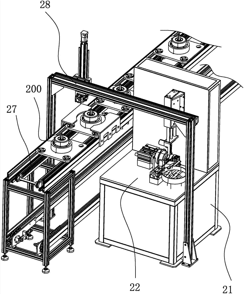
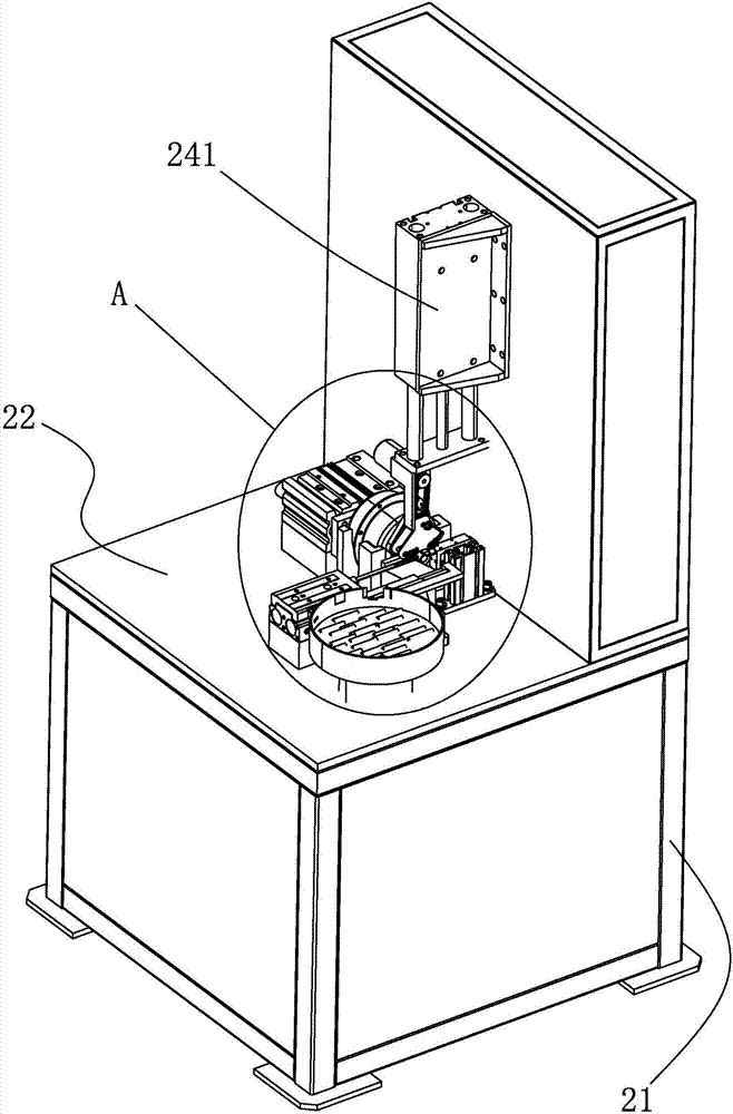
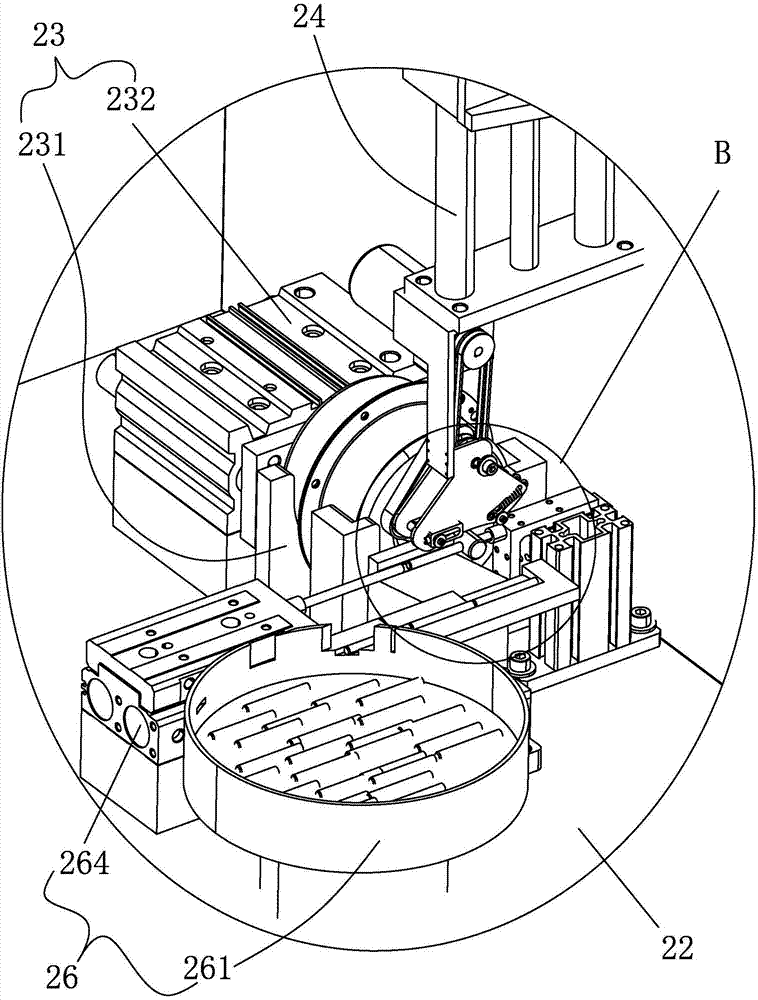
[0029] Such as Figure 1 to Figure 9 As shown, a motor pin press-in device in this embodiment includes a frame 21, and the frame 21 is provided with a horizontal table 22, and the horizontal table 22 is provided with a motor for positioning and clamping. 200 motor positioning mechanism 23, the frame 21 is provided with a motor shaft driving device 24 that drives the motor shaft 201 to rotate, and the horizontal workbench 22 is provided with a motor shaft that can be inserted into the through hole 202 on the motor shaft 201 The positioning mechanism 25, the horizontal workbench 22 is also provided with a pin automatic pressing device 26 for pressing the pin 203 into the through hole 202 on the motor shaft 201 . In the present invention, the motor 200 is first positioned and clamped on the motor positioning mechanism 23, and then the motor shaft driving...


PUM


Abstract

The invention discloses motor pin pressing-in equipment. The motor pin pressing-in equipment comprises a rack, the rack is provided with a horizontal workbench, the horizontal workbench is provided with a motor positioning mechanism for positioning and clamping a motor, the rack is provided with a motor rotating shaft driving device for driving a motor rotating shaft to rotate, the horizontal workbench is provided with a motor rotating shaft positioning mechanism capable of being inserted into a through hole in the motor rotating shaft, and the horizontal workbench is furthermore provided with an automatic pin pressing-in device for pressing a pin into the through hole in the motor rotating shaft. According to the motor pin pressing-in equipment, firstly, the motor is positioned and clamped to the motor positioning mechanism; then, the motor rotating shaft drive device drives the motor rotating shaft to rotate, and the motor rotating shaft stops rotating and is positioned when the through hole in the motor rotating shaft is opposite to a positioning rod of the motor rotating shaft positioning mechanism; and then, the automatic pin pressing-in device presses the pin into the through hole in the motor rotating shaft. The motor pin pressing-in equipment has the advantages of being simple in structure, high in automated degree, small in number of processes and high in work efficiency.

Description

【Technical field】 [0001] The invention relates to the field of motor assembly, in particular to a motor pin press-in device. 【Background technique】 [0002] On motor shafts such as range hoods and electric fans, in order to facilitate the rotation of the fan blade relative to the motor shaft, a hole is usually opened on the motor shaft, and then a pin is assembled on the hole. The existing manual semi-automatic pin pressing equipment has low degree of automation and low efficiency, and it is difficult to meet the demand for mass production. [0003] The present invention researches and proposes aiming at the deficiencies in the prior art. 【Content of invention】 [0004] The technical problem to be solved by the present invention is to provide a motor pin pressing device with simple structure, high degree of automation and high efficiency. [0005] In order to solve the above technical problems, a motor pin pressing device of the present invention includes a frame, the fr...

Claims


Application Information

Patent Timeline
Patent Type & Authority Applications(China)
IPC IPC(8): B23P21/00
CPCB23P19/001B23P19/027Y02T10/64
Inventor 罗躜黄安全李义陶国桢李安平傅洪波丁定
Owner GUANGDONG HANDSOME INTELLIGENT EQUIP CO LTD
Learn More