
Stirring cup body and cell wall breaking machine

A mixing cup and wall breaking machine technology, which is applied in home appliances, applications, kitchen utensils, etc., can solve the problems of large noise in the mixing cup, insufficient whipping, and lumps, so as to achieve high crushing efficiency and improve whipping Performance, the effect of improving whipping performance

Active Publication Date: 2017-09-15
GUANGDONG MIDEA CONSUMER ELECTRICS MFG CO LTD +1
View PDF2 Cites 1 Cited by
  • Summary
  • Abstract
  • Description
  • Claims
  • Application Information

AI Technical Summary

Problems solved by technology

In the process of beating the ingredients, the existing wall-breaker will produce insufficient beating and lumps, and the final crushing efficiency of the ingredients is not high, and the noise in the mixing cup is very loud during the beating process

Method used


Image

  • Stirring cup body and cell wall breaking machine
  • Stirring cup body and cell wall breaking machine
  • Stirring cup body and cell wall breaking machine

Examples


Embodiment 1

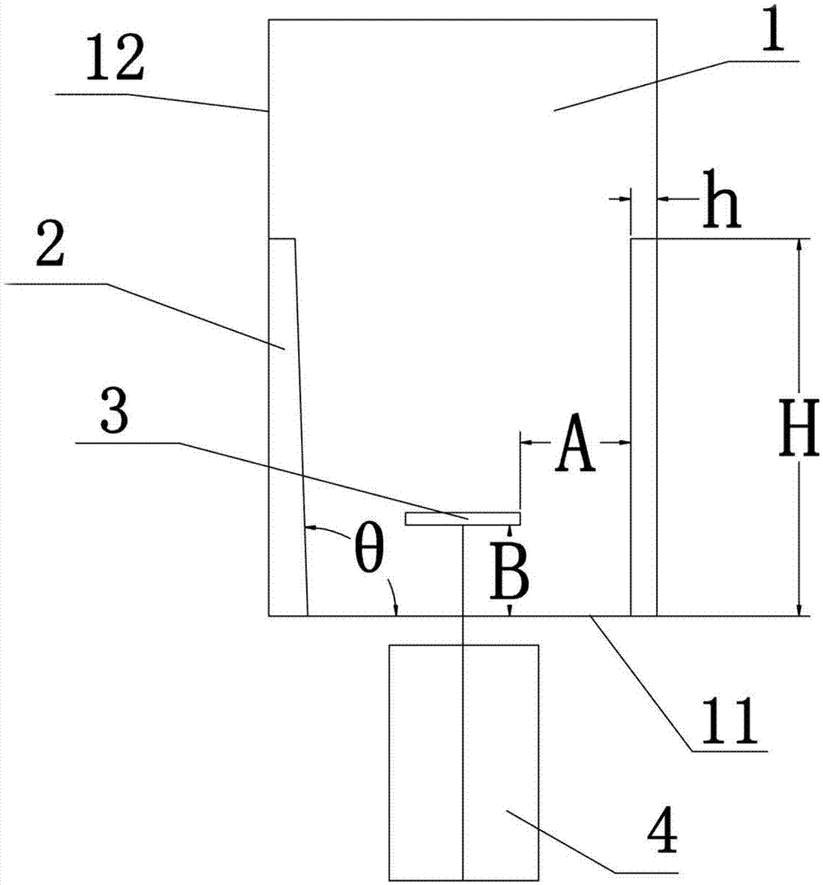
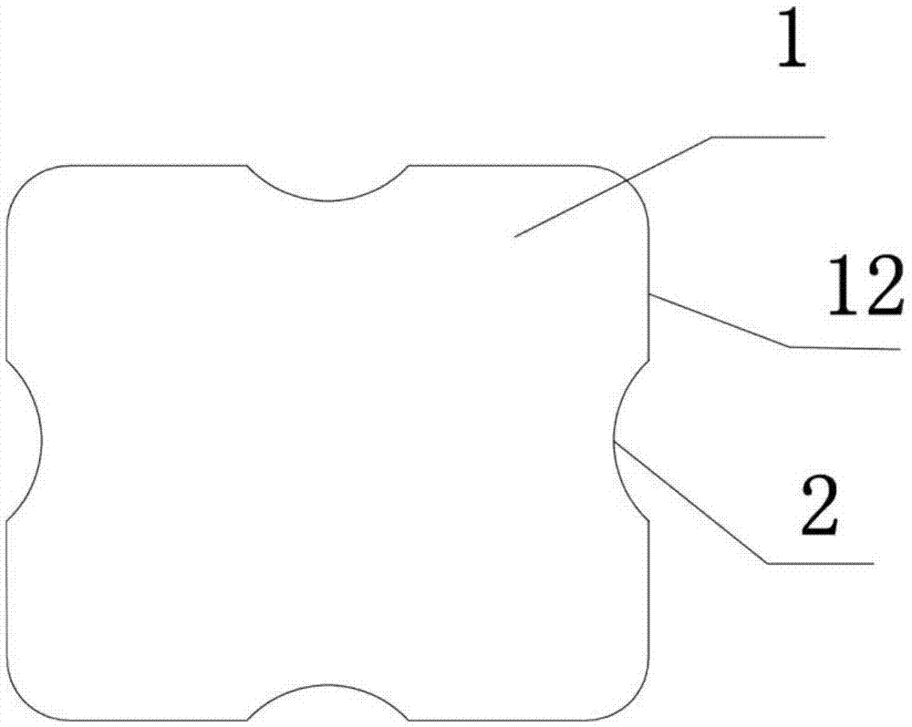
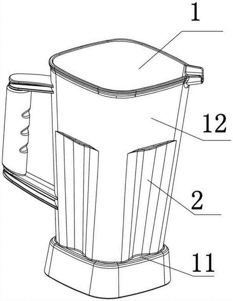
[0047] Such as Figure 1 ~ Figure 3 As shown, a stirring cup of this embodiment is detachably installed on the main machine of the wall breaker, and a stirring knife 3 is installed on the inner side of the bottom wall 11; the inner side of the side wall 12 of the stirring cup 1 A plurality of spoiler ribs 2 are integrally connected. The spoiler ribs 2 are linear convex ribs formed by indenting the side wall 12 of the stirring cup body 1 in the direction of the central axis of the stirring cup body 1. The cross-sections of each height of the linear convex ribs are The shapes are the same, the heights of the depressions are equal, but the width of the cross-section gradually decreases from the top; the plurality of spoiler ribs 2 are all in a linear structure and arranged longitudinally on the inner side of the side wall 12 of the mixing cup body 1. One end of the rib 2 is located on the inner surface of the bottom wall 11 of the stirring cup body 1, and the other end is located...

Embodiment approach 1

[0048] Embodiment 1: The cross-section of the side of the spoiler 2 located in the stirring cup body 1 is arc-shaped, that is, the side of the spoiler 2 located in the stirring cup 1 is an arc-shaped structure. The curved structure and the curved surface structure have uniform whipping strength. During the working process of the mixing cup body, when the ingredients collide with the spoiler ribs in the stirring cup body, it can reduce rigid collision, reduce noise, and is easy to clean.

Embodiment approach 2

[0049]Embodiment 2: The cross-section of the spoiler rib 2 is polygonal, and the lengths of the sides of the polygon located in the stirring cup body 1 are equal, and every two adjacent sides pass through an arc transition; that is, the spoiler rib 2 is located in the stirring cup One side of the body 1 is a multi-ribbon structure. This structure has high whipping strength, and each side can effectively apply force, which can increase the collision area between the ingredients and the spoiler ribs during the whipping process, and avoid the same area of ​​the spoiler ribs. Repeated rigid collision reduces noise. The cross-section of the spoiler rib 2 in this embodiment is preferably triangular, and the lengths of the two sides of the triangle inside the stirring cup 1 are equal, and the included angle is not less than 90°.

[0050] Such as figure 2 with image 3 As shown, a plurality of spoiler ribs 2 in this embodiment are uniformly arranged around the central axis of the s...


PUM


Abstract

The invention relates to a stirring cup body and a cell wall breaking machine. The stirring cup body is arranged on a host engine of the cell wall breaking machine; a stirring knife is arranged on the inner side face of the bottom wall of the stirring cup body; a plurality of turbulence ribs are integrally connected to the inner side face of the sidewall of the stirring cup body; the turbulence ribs are bumps which are defined as the sidewall of the stirring cup body sinks towards the direction of a central axis of the stirring cup body; the plurality of turbulence ribs are represented as linear structures and are longitudinally distributed on the inner side face of the sidewall of the stirring cup body; and the ratio of longitudinal length of the turbulence ribs to height of the turbulence ribs, which protrude the inner side face of the sidewall of the stirring cup body, is at 0.67-100. According to the stirring cup body provided by the invention, since the ratio of longitudinal length of the turbulence ribs to height of the turbulence ribs, which protrude the inner side face of the sidewall of the stirring cup body, is at 0.67-100, the stirring cup body, in a process of stirring and beating food materials, is higher in grinding efficiency, so that stirring performance is enhanced.

Description

technical field [0001] The invention relates to the technical field of small household appliances, in particular to a stirring cup body and a wall breaking machine. Background technique [0002] The commonly used wall breaking machine combines the functions of juicer, soybean milk machine, ice cream machine, grinder and other products. It can achieve the function of one machine with multiple functions. It can instantly break down the cell wall of food and release phytochemicals. In the process of beating the ingredients, the existing wall-breaker will produce insufficient beating and lumps, and the final crushing efficiency of the ingredients is not high, and the noise in the mixing cup is very loud during the beating process . Contents of the invention [0003] The technical problem to be solved by the present invention is to provide a stirring cup and a wall breaking machine for the deficiencies of the prior art. [0004] The technical solution of the present invention...

Claims


Application Information

Patent Timeline
Patent Type & Authority Applications(China)
IPC IPC(8): A47J43/046A47J43/07
CPCA47J43/046A47J43/0722
Inventor 刘榕曾祥和陈炜杰徐建飞
Owner GUANGDONG MIDEA CONSUMER ELECTRICS MFG CO LTD
Learn More