Coupling coil and magnetic core structure used for underwater wireless charging and underwater wireless charging system

A coupling coil and wireless charging technology, applied in the direction of transformer/inductor core, transformer/inductor coil/winding/connection, transformer/inductor parts, etc., can solve the problem of unsuitable coil structure, increase transmission distance, The coil radius cannot be increased without limit, etc., to achieve the effect of easy structure and low cost

Inactive Publication Date: 2017-09-12
青岛中科瑞信无线充电技术有限公司
View PDF5 Cites 18 Cited by
  • Summary
  • Abstract
  • Description
  • Claims
  • Application Information

AI Technical Summary

Problems solved by technology

However, the radius of the coil cannot be increased without limit, so there is a contradiction between increasing the transmission distance and reducing the volume of the system
[0006] (2) Unstable power transmission
Different from the wireless charging system on land, due to the influence of the water flow, the relative position and distance between the transmitting coil and the receiving coil are changing in real time, and even relative rotation will occur. Therefore, the coil structure of the wireless charging system on land is not suitable for underwater Next wireless charging

Method used


Image

  • Coupling coil and magnetic core structure used for underwater wireless charging and underwater wireless charging system
  • Coupling coil and magnetic core structure used for underwater wireless charging and underwater wireless charging system
  • Coupling coil and magnetic core structure used for underwater wireless charging and underwater wireless charging system

Examples


Embodiment Construction

[0037] The present invention will be further described below in conjunction with the accompanying drawings and embodiments.

[0038] It should be pointed out that the following detailed description is exemplary and intended to provide further explanation to the present application. Unless defined otherwise, all technical and scientific terms used herein have the same meaning as commonly understood by one of ordinary skill in the art to which this application belongs.

[0039] It should be noted that the terminology used here is only for describing specific implementations, and is not intended to limit the exemplary implementations according to the present application. As used herein, unless the context clearly dictates otherwise, the singular is intended to include the plural, and it should also be understood that when the terms "comprising" and / or "comprising" are used in this specification, they mean There are features, steps, operations, means, components and / or combinatio...


PUM


Abstract

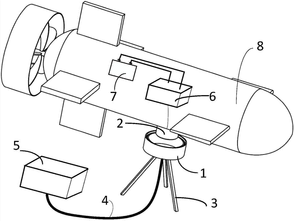
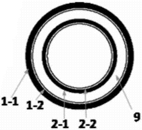
The invention discloses a coupling coil and magnetic core structure used for underwater wireless charging and an underwater wireless charging system. The coupling coil and magnetic core structure comprises a transmitting end and a receiving end. The transmitting end and receiving end comprise annular-shaped magnetic core skeletons and coils disposed on the skeletons in a coiled manner. The transmitting end coil and the receiving end coil are in an embedded arrangement, and a certain gap is arranged therebetween, and the transmitting end coil and the receiving end coil are coupled with each other, and a coupling magnetic field is in a radial direction. The transmitting end coil and the receiving end coil are coupled with each other by the radial magnetic field, and an object of realizing wireless electric energy transmission is achieved.

Description

technical field [0001] The invention relates to a coupling coil and magnetic core structure and system applied to underwater wireless charging. Background technique [0002] The exploration and scientific research activities in the sea are inseparable from the support of underwater electromechanical equipment. As a main power supply method for underwater electromechanical equipment, the power battery pack has the characteristics of stable voltage, reliable power supply, and flexible loading and unloading; however, it needs to be recharged when the battery pack is exhausted. Traditionally, a conductor-contact wet-swap power interface is used to connect underwater equipment to a power source for charging. Although this power transmission interface technology is relatively mature and can be used for a long time on the seabed after one plug and unplug, it is difficult to support future high-density and high-intensity marine scientific research for a long time due to factors suc...

Claims


Application Information

Patent Timeline
Patent Type & Authority Applications(China)
IPC IPC(8): H02J50/10H02J7/00H01F27/28H01F27/24
CPCH02J50/10H01F27/24H01F27/2895H02J7/025
Inventor 刘志珍曾浩黑桐周博岳增凯
Owner 青岛中科瑞信无线充电技术有限公司
Why Eureka
Try Eureka