Inertia driving rotor isolation mechanism

An isolation mechanism and inertial drive technology, applied in the direction of weapon accessories, fuzes, offensive equipment, etc., can solve problems such as potential safety hazards, unreasonable use of space, and incomplete alignment of explosion sequences, so as to reduce the occurrence of accidents and accidents Detonation situation, avoiding the effect of incomplete alignment

Active Publication Date: 2017-09-12
湖北三江航天红林探控有限公司
View PDF6 Cites 2 Cited by
  • Summary
  • Abstract
  • Description
  • Claims
  • Application Information

AI Technical Summary

Problems solved by technology

First of all, when the safety of the isolation mechanism is released and the movement is in place, the isolation mechanism does not have a locking function. In the vibration environment, it is easy to cause the isolation mechanism to be misplaced, and eventually lead to incomplete alignment of the explosion sequence; secondly, the two-stage safety of the horizontal rotor type isolation mechanism If the components are misplaced, the size of the mechanism will be larger and the space utilization will be unreasonable; thirdly, the existing horizontal rotor type isolation mechanism usually cannot accurately identify and display the state of the isolation mechanism, which is not conducive to the operator to judge the state of the isolation mechanism , indirect security risks
The above-mentioned defects limit the application of the horizontal rotor type isolation mechanism to a certain extent, have certain influence on the safety and practicability of the isolation mechanism, and cannot fully satisfy the safe use of the fuze.

Method used


Image

  • Inertia driving rotor isolation mechanism
  • Inertia driving rotor isolation mechanism
  • Inertia driving rotor isolation mechanism

Examples


Embodiment Construction

[0049] In order to make the object, technical solution and advantages of the present invention clearer, the present invention will be further described in detail below in conjunction with the accompanying drawings and embodiments. It should be understood that the specific embodiments described here are only used to explain the present invention, not to limit the present invention.

[0050] In addition, the technical features involved in the various embodiments of the present invention described below can be combined with each other as long as they do not constitute a conflict with each other.

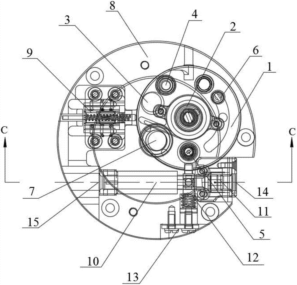
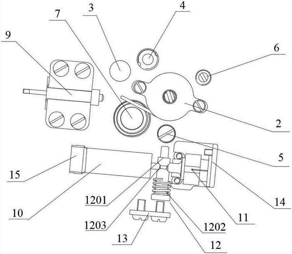
[0051] figure 1 It is a schematic diagram of the overall structure of the inertia-driven rotor type isolation mechanism of the embodiment of the present invention; figure 2 It is a disassembly diagram of the overall structure of the isolation mechanism of the embodiment of the present invention; image 3 It is a bottom view of the rotor structure of the isolation mechanism of the emb...


PUM


Abstract

The invention discloses an inertia driving rotor isolation mechanism, and belongs to the technical field of fuse safety mechanism. The isolation mechanism comprises a main body provided with a rotor hole, and a rotor embedded in the rotor hole; the rotor and the main body are provided with holes for accommodating such parts as a manual pin pusher, an inert safety part, a lock pin, a conversion switch, a fire transfer part and an explosion propagation part; and through preferential structural parts and preferential hole positions, even if the isolation mechanism has a larger isolation relief turning angle, the state of the isolation mechanism can be precisely identified and returned, and the isolation mechanism can be locked in the state in each state. Through settings, on the one hand, the safety of the mechanism in the safety state is guaranteed, the alignment of detonation sequences in an arming state is guaranteed, and the detonation efficiency is greatly improved; and on the other hand, such parts as the conversion switch is applied to effectively identify the state of the isolation mechanism to return to the control system, so that the safety and the detonation efficiency of the isolation mechanism can be further improved.

Description

technical field [0001] The invention belongs to the technical field of fuze insurance mechanisms, and in particular relates to an inertia-driven rotor isolation mechanism. Background technique [0002] Explosives are a general term for disposable components and devices that contain gunpowder or explosives, which burn or explode after being stimulated by the outside world to ignite gunpowder, detonate explosives, or perform mechanical work. An isolation mechanism is usually set in the pyrotechnics, and its function is to isolate the sensitive pyrotechnic elements in the explosion sequence from the next-level pyrotechnic elements at ordinary times, so as to ensure that the fuze does not ignite when the pyrotechnics accidentally act in advance, thereby avoiding Ammunition exploded prematurely, endangering the safety of personnel and equipment. [0003] The safety of the fuze involves the whole life cycle of the fuze, such as demonstration, design, manufacture, inspection and a...

Claims


Application Information

Patent Timeline
Patent Type & Authority Applications(China)
IPC IPC(8): F42C15/24F42C15/21
CPCF42C15/21F42C15/24
Inventor 李响陈亮雷林
Owner 湖北三江航天红林探控有限公司
Why Eureka
Try Eureka