
Magnetic blow-out system, arc extinguishing device, single-pole circuit breaker and multi-pole circuit breaker

A circuit breaker and magnetic blowing technology, which is applied in the field of multi-pole circuit breakers, magnetic blowing systems, and circuit breaker arc extinguishing devices, can solve the problems of limited application occasions and inability to adapt to small current applications, and achieve simple structure and difficult to break The effect of small current and accelerated extinguishing

Active Publication Date: 2017-09-08
ANDELI GRP
View PDF6 Cites 3 Cited by
  • Summary
  • Abstract
  • Description
  • Claims
  • Application Information

AI Technical Summary

Problems solved by technology

[0006] Therefore, the technical problem to be solved by the present invention is to overcome the defects in the prior art that the application occasions are limited and cannot adapt to small current applications, thereby providing a magnetic blowing system
[0007] Another technical problem to be solved by the present invention is to overcome the defects in the prior art that the application occasions are limited and cannot adapt to small current applications, thereby providing an arc extinguishing device
[0008] Another technical problem to be solved by the present invention is to overcome the defects in the prior art that the application occasions are limited and cannot adapt to small current applications, thereby providing a single-pole circuit breaker

Method used


Image

  • Magnetic blow-out system, arc extinguishing device, single-pole circuit breaker and multi-pole circuit breaker
  • Magnetic blow-out system, arc extinguishing device, single-pole circuit breaker and multi-pole circuit breaker
  • Magnetic blow-out system, arc extinguishing device, single-pole circuit breaker and multi-pole circuit breaker

Examples


Embodiment Construction

[0041] The technical solutions of the present invention will be clearly and completely described below in conjunction with the accompanying drawings. Apparently, the described embodiments are some of the embodiments of the present invention, but not all of them. Based on the embodiments of the present invention, all other embodiments obtained by persons of ordinary skill in the art without making creative efforts belong to the protection scope of the present invention.

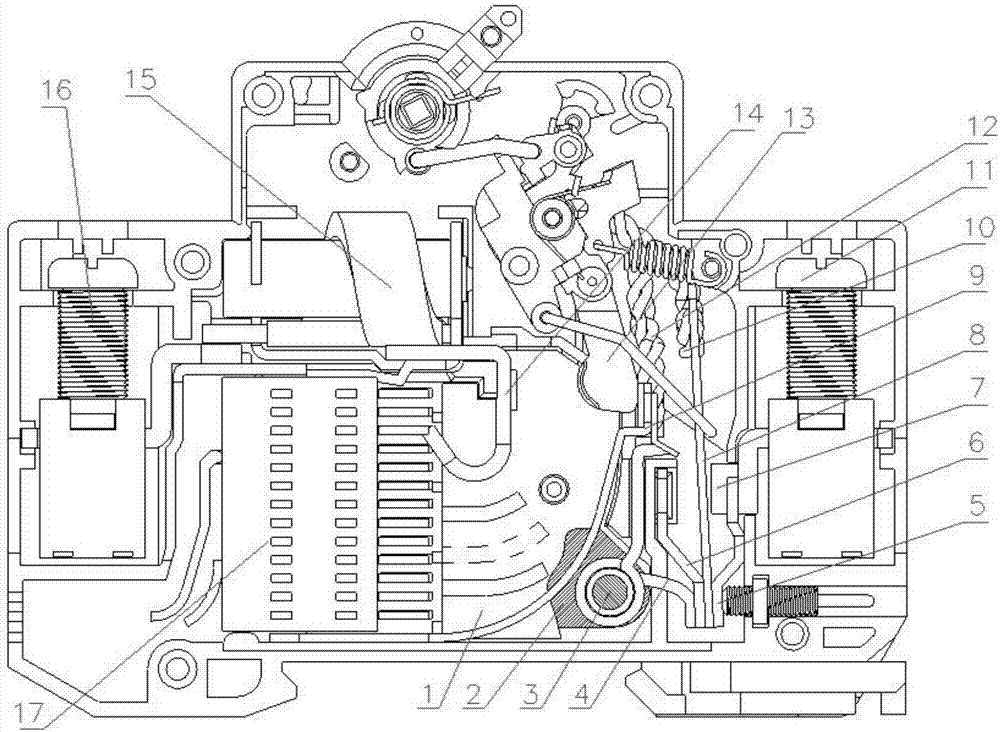
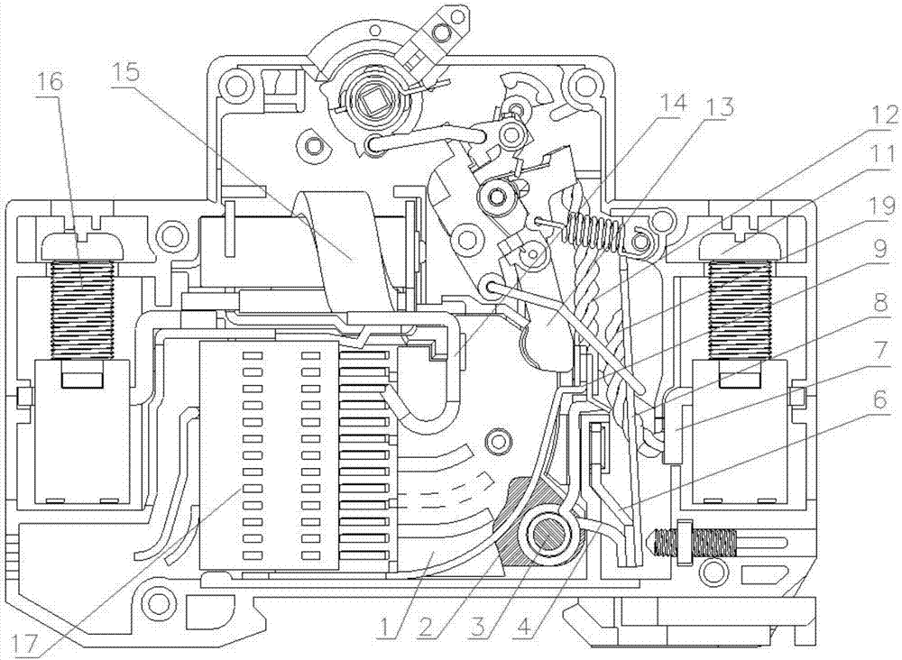
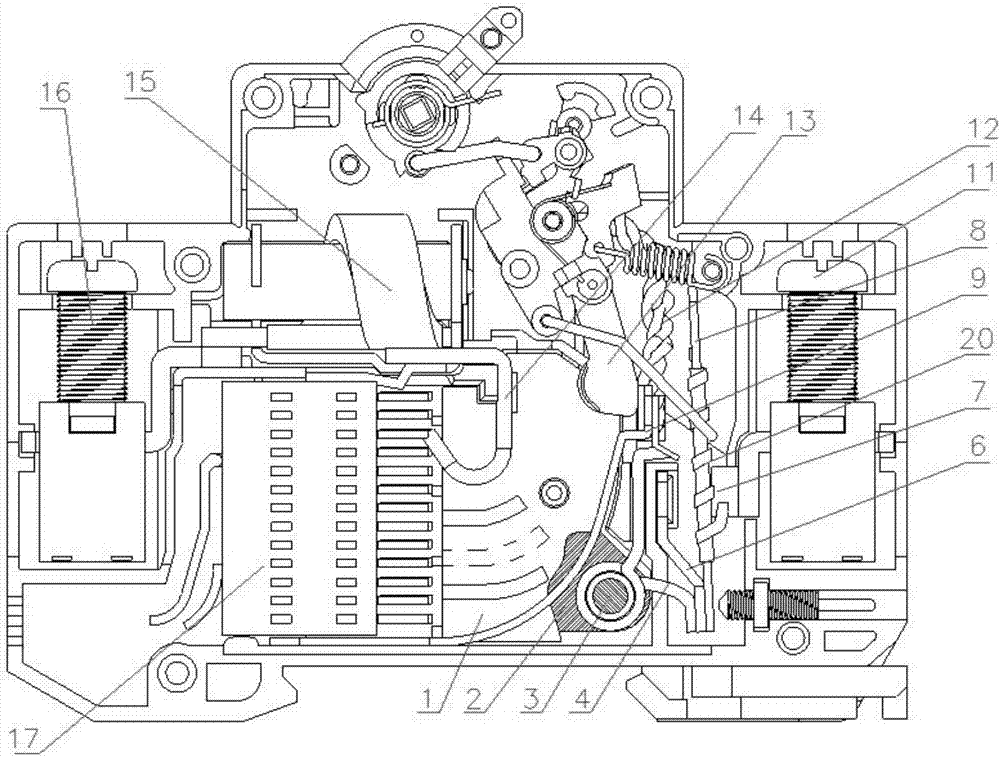
[0042] figure 1The applicable current range of the single-pole circuit breaker shown is 16A-63A. The single-pole circuit breaker includes a moving contact 13 and a static contact 14, and a first terminal screw 11 and a Second terminal screw 16. The first terminal screw 11 and the second terminal screw 16 are the movable terminal and the static terminal. The first terminal screw 11 and the second terminal screw 16 are respectively used to connect the first connecting wire and the second connecting wire extern...


PUM


Abstract

The invention provides a magnetic blow-out system, an arc extinguishing device, a single-pole circuit breaker and a multi-pole circuit breaker. The magnetic blow-out system comprises a magnetic blow-out coil used for blowing arcs generated between a moving contact and a static contact of a circuit breaker to an arc extinguishing chamber, the magnetic blow-out coil is arranged on a shunting branch of a circuit breaker main circuit with set current or is connected to the circuit breaker main circuit with set current in series. The current flows through the magnetic blow-out coil when the circuit is connected by the moving contact and the static contact so as to generate magnetic flux. When the contacts are disconnected and arcs are generated, the magnetic blow-out coil can push the arcs to move towards the arc extinguishing chamber due to the magnetic flux generated when the current flow through. The technical scheme is simple in structure and capable of adapting to application occasions with small current. In addition, the magnetic blow-out system has no requirement for the polarity of a wiring terminal, solves a problem that small current is difficult to be disconnected, can be applied to direct current and alternating current occasions, meets requirements of a photovoltaic power generation system and the like for a miniature circuit breaker and adapts to development requirements of a new energy industry in the future.

Description

technical field [0001] The invention relates to the technical field of low-voltage electrical appliances, and specifically relates to a magnetic blowing system. The invention also designs an arc extinguishing device for a circuit breaker, a single-pole circuit breaker and a multi-pole circuit breaker. Background technique [0002] Arc is a kind of gas discharge phenomenon, and an arc will be generated when the moving contact and the static contact in the switching device are disconnected. Arc is a free gas with high temperature and high conductivity. It not only has a great destructive effect on the contacts, but also prolongs the time for disconnecting the circuit, which has a great impact on the safe operation of the power supply and distribution system. [0003] Using an external magnetic field to push the arc to the arc extinguishing chamber to realize forced arc extinguishing is a common arc extinguishing method for low-voltage electrical appliances. In the DC field, p...

Claims


Application Information

Patent Timeline
IPC IPC(8): H01H9/44
CPCH01H9/44
Inventor 黄真陈武奇刘忠卓琴侠王远向国庆王敏
Owner ANDELI GRP
Learn More