High-repetitive frequency pulse radar extension distance measurement range waveform design method
A technology of pulse radar and waveform design, which is applied in measuring devices, radio wave measurement systems, radio wave reflection/reradiation, etc. It can solve the problems of duty cycle and average power drop, distance ambiguity, etc., and maintain the duty cycle and average power, high duty cycle and average power, the effect of improving the distance measurement range without ambiguity
- Summary
- Abstract
- Description
- Claims
- Application Information
AI Technical Summary
Problems solved by technology
Method used
Image
Examples
specific Embodiment approach 1
[0019] Specific implementation mode one: a waveform design method for extending the ranging range of a high-repetition pulse radar is implemented according to the following steps:
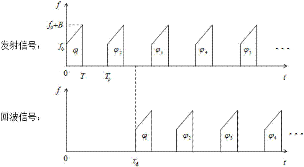
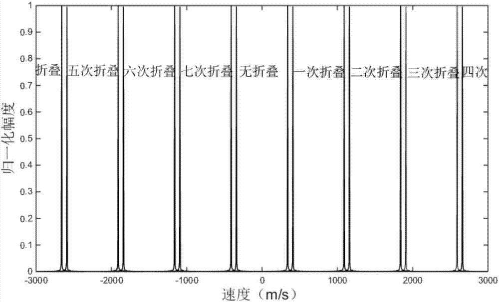
[0020] High repetition frequency pulse signal can achieve a large range of unambiguous speed measurement, set: 0~V, assuming that the maximum speed of the target in the current detection situation is V 1 , and V 1 < V, the Doppler detection range is partially wasted. At this time, the intra-pulse linear frequency modulation inter-pulse phase modulation pulse signal is used, and the parameters are designed according to the speed relationship, so that the Doppler frequency of the echoes with different folding distances can be moved to different areas, and the echoes with different folding distances can be adjusted in the Doppler dimension. separate.
[0021] The processing process of intra-pulse linear frequency modulation and inter-pulse phase modulation pulse signal is basically the same as that ...
specific Embodiment approach 2
[0026] Specific embodiment two: the difference between this embodiment and specific embodiment one is: in the step one, according to the maximum speed of the target in the radar detection environment is V 1 and the maximum detection speed V of the high repetition frequency pulse signal, the specific process of determining the parameter α, and determining the corresponding relationship between the speed range and the target’s true speed and distance folding times is as follows:
[0027] Assume Take M to be the largest integer smaller than M', and take α=1 / M.
[0028] Assuming that the maximum speed of the target is 1 / M' of the maximum detection speed of Doppler, M is the largest integer smaller than M', so the Doppler range can be divided into M parts, and the echoes with different folding times can be obtained by parameter design. They fall into different areas respectively, and the range of unambiguous ranging is expanded by M times.
[0029] Velocity range for target echo...
specific Embodiment approach 3
[0031] Embodiment 3: The difference between this embodiment and Embodiment 1 or 2 is that in the second step, according to the α determined in Step 1, the pulse-to-pulse phase modulation is performed on the chirp signal to obtain the intra-pulse chirp pulse-to-pulse phase The specific process of modulating the pulse signal is:
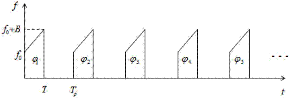
[0032] Such as figure 1 As shown, the signal used in the present invention is an intra-pulse linear frequency modulation inter-pulse phase modulation pulse signal, and the pulse signal adopts a linear frequency modulation pulse. In order to solve the distance ambiguity problem caused by pulse cycle repetition, a secondary phase modulation is performed between the pulse signals. The invention adopts the signal form as follows:
[0033]
[0034]
[0035] Among them, n is the frequency modulation pulse number in the coherent accumulation cycle, N is the number of coherent accumulation cycles, k is the frequency modulation slope, T is the frequency ...
PUM
 Abstract
Description
Claims
Application Information
 - R&D
- Intellectual Property
- Life Sciences
- Materials
- Tech Scout
- Unparalleled Data Quality
- Higher Quality Content
- 60% Fewer Hallucinations
Browse by: Latest US Patents, China's latest patents, Technical Efficacy Thesaurus, Application Domain, Technology Topic, Popular Technical Reports.
© 2025 PatSnap. All rights reserved.Legal|Privacy policy|Modern Slavery Act Transparency Statement|Sitemap|About US| Contact US: help@patsnap.com


