a bioretention pond
A technology of bioretention ponds and retention ponds, which is applied in the field of surface runoff treatment, can solve the problems of easy occurrence of dead seedlings, incompatibility of drainage requirements and landscape requirements, etc.
- Summary
- Abstract
- Description
- Claims
- Application Information
AI Technical Summary
Problems solved by technology
Method used
Image


Examples
Embodiment 1
[0050] In practical application, this embodiment builds a bioretention pond in the reconstruction area, and the water storage capacity of the bioretention pond is 0.75m 3 ; The specific implementation is as follows:
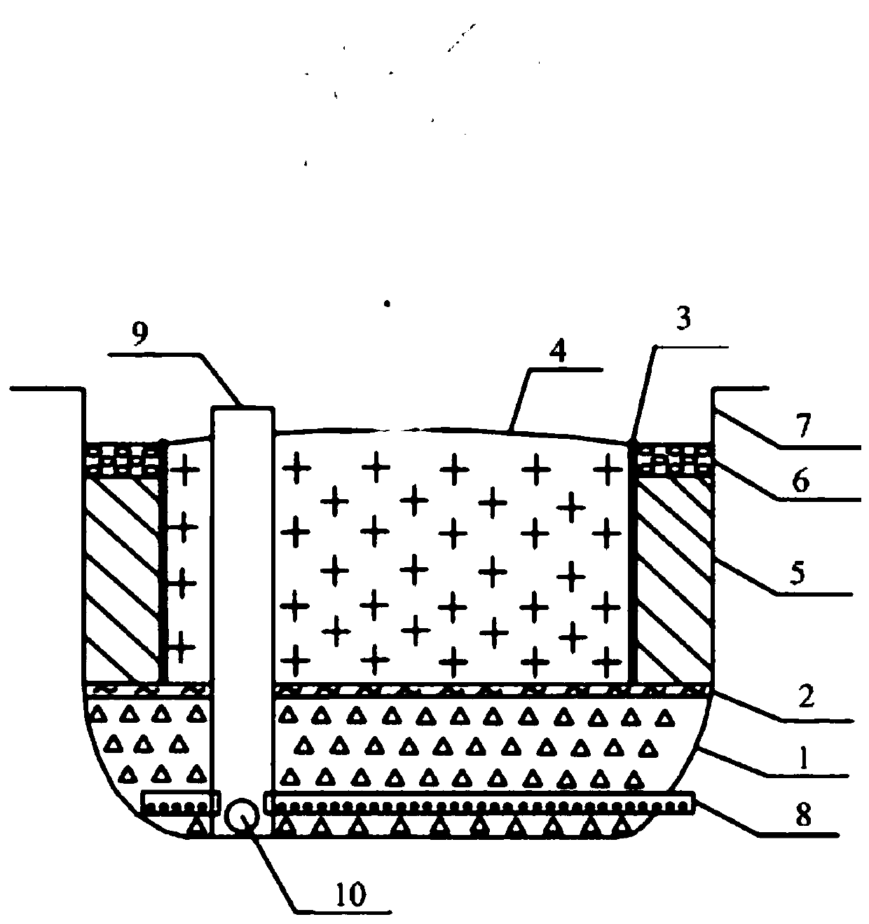
[0051] Excavate a square foundation pit with a length of 3m, a width of 2m, and a depth of about 97.5cm in the reconstruction area, and lay impermeable geotextiles around the foundation pit and at the bottom; the bioretention tank includes: gravel base 1, separation layer 2, and isolation components 3. Planting soil layer 4, filter material layer 5; wherein,
[0052] The crushed stone base 1 is located at the bottom of the detention tank, and is used for load-bearing and infiltrating water flow; the thickness of the crushed stone base is 30cm, and the crushed stone can be open-graded crushed stone, and the crushing value is ≤25%; The particle size of the gravel is 5-25mm.
[0053] The separation layer 2 is located above the crushed stone base 1; the separation ...
Embodiment 2
[0075] In practical application, this embodiment builds a bioretention pond in the reconstruction area, and the water storage capacity of the bioretention pond is 0.9m 3 ; The specific implementation is as follows:
[0076] In the reconstruction area, a circular foundation pit with a radius of 1m and a depth of about 102cm was excavated, and impermeable geotextiles were laid around and at the bottom of the foundation pit; Soil layer 4, filter material layer 5; wherein,
[0077] The crushed stone base 1 is located at the bottom of the detention tank, and is used for load bearing and seepage flow; the thickness of the crushed stone base is 25cm, and the crushed stone can be open-graded crushed stone, and the crushing value is ≤25%; The particle size of the gravel is 5-25mm.
[0078] The separation layer 2 is located above the gravel base 1; the separation layer 2 is a permeable geotextile.
[0079] The isolation component 3 is located above the separation layer 2, and there i...
Embodiment 3
[0100] In practical application, this embodiment builds a bioretention pond in the reconstruction area, and the water storage capacity of the bioretention pond is 0.7m 3 ; The specific implementation is as follows:
[0101] Excavate an equilateral triangular foundation pit with a side length of 4m and a depth of 90cm in the reconstruction area, and lay impermeable geotextiles around and at the bottom of the foundation pit; Planting soil layer 4, filter material layer 5; wherein,
[0102] The crushed stone base 1 is located at the bottom of the detention tank, and is used for load bearing and seepage flow; the thickness of the crushed stone base is 20cm, and the crushed stone can be open-graded crushed stone, and the crushing value is ≤25%; The particle size of the gravel is 5-25 mm.
[0103] The separation layer 2 is located above the gravel base 1; the separation layer 2 is a permeable geotextile.
[0104] The isolation component 3 is located above the separation layer 2, ...
PUM
| Property | Measurement | Unit |
|---|---|---|
| thickness | aaaaa | aaaaa |
| particle diameter | aaaaa | aaaaa |
| thickness | aaaaa | aaaaa |
Abstract
Description
Claims
Application Information
 - R&D
- Intellectual Property
- Life Sciences
- Materials
- Tech Scout
- Unparalleled Data Quality
- Higher Quality Content
- 60% Fewer Hallucinations
Browse by: Latest US Patents, China's latest patents, Technical Efficacy Thesaurus, Application Domain, Technology Topic, Popular Technical Reports.
© 2025 PatSnap. All rights reserved.Legal|Privacy policy|Modern Slavery Act Transparency Statement|Sitemap|About US| Contact US: help@patsnap.com