Eureka AIR delivers breakthrough ideas for toughest innovation challenges, trusted by R&D personnel around the world.

Rotary distributor

A technology of rotating distributor and distribution plate, applied in rotary conveyors, conveyors, transportation and packaging, etc., can solve problems such as insufficient connection, stringing, poor stability, etc., to achieve stable and reliable device, high positioning accuracy, Noise reduction effect

Active Publication Date: 2017-09-08
湖北邦业饲料有限公司
View PDF7 Cites 0 Cited by
  • Summary
  • Abstract
  • Description
  • Claims
  • Application Information

AI Technical Summary

Problems solved by technology

However, this patent, like many patents in the prior art, does not take into account that the rotating discharge pipe produces inertia during work, resulting in poor stability during discharge. The connection with the discharge pipe has not been treated, so that the connection between the two is not tight enough, and the material is easy to accumulate in the rotary distributor, resulting in the problem of cross-feeding

Method used


Image

  • Rotary distributor
  • Rotary distributor
  • Rotary distributor

Examples


Embodiment 1

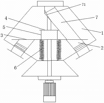
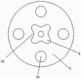
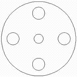
[0021] Such as Figure 1-4 As shown, a rotary distributor includes an upper cone 1, a distribution plate is installed on the lower part of the upper cone 1, and a plurality of evenly distributed distribution chambers are arranged on the distribution disk, and a sealing cover is installed on the lower part of the distribution chamber. A motor is installed on the lower part of the sealing cover, a reducer is installed on the upper end of the motor, and a rotating shaft is installed on the upper end of the reducer. A feeding pipe 7 is installed on the mouth, and the feeding pipe 7 is fixed on the rotating shaft. A flexible hose 2 is installed on each distribution bin, and one end of the flexible hose 2 is fixed on the fixing hole 31 of the inner fixing plate 3 of the upper cone 1. , and the other end protrudes from the upper cone 1 to connect with the feed pipe of the storage bin; the fixed plate 3 is fixed with a pattern plate 4, and the edge of the pattern plate 4 is provided w...

Embodiment 2

[0023] The difference between embodiment 2 and embodiment 1 is that in order to reduce the load on the motor, we set up a pneumatic cylinder on the lower part of the fixed plate 3, and the pneumatic cylinder, reducer, and motor are all connected to the PLC controller. When the feed pipe rotates to the flexible When the hose is in place, the pneumatic cylinder lifts the fixed plate 3, and the feeding pipe 7 is stuck in the arc groove of the pattern plate 4 for accurate positioning. When the feeding is completed, the pneumatic cylinder shrinks the feeding pipe 7 and the flexible soft The tube 2 is detached, and the feeding tube will not touch the fixed plate 3 when it rotates under the driving action of the rotating shaft, which can effectively reduce noise. The rotation of the rotating shaft and how to position the feeding tube belong to the prior art, and will not be described in detail here repeat.

[0024] In order to ensure that the feed pipe 7 and the flexible hose 2 are c...


PUM


Abstract

The invention relates to the technical field of fodder production equipment, in particular to a rotary distributor. The rotary distributor provided by the invention is characterized in that a flexible hose is mounted on each distribution bin; one end of each flexible hose is fixed to a fixing hole in a fixing plate in an upper cone, and the other end of each flexible hose stretches out of the upper cone to be connected with a feeding tube of a storage bin; a pattern plate is fixedly arranged on the fixing plate, arc grooves are formed in the edge of the pattern plate, the arc grooves and the distribution bins are in one-to-one correspondence, and fixing plate and the pattern plate allow a rotary shaft to penetrate through and are fixed to a distribution disc through springs; and when the feeding tubes are located in the arc grooves, the discharging ends of the feeding tubes are connected with the feeding ends of the flexible hoses fixed to the fixing plate, and when the feeding tubes rotate rout of the arc grooves, the feeding tubes are disengaged from the fixing plate. The rotary distributor provided by the invention is stable, reliable, high in positioning precision, low in noise, and capable of preventing material blending.

Description

technical field [0001] The invention relates to the technical field of feed production equipment, in particular to a rotary distributor. Background technique [0002] The rotary distributor is a device that can automatically adjust and position the material and input it to the pre-positioned position using the self-flow of the material. It is a remote control device that feeds materials from one point to multiple points. It is widely used in raw material storage and feed processing. The intermediate products of the factory enter the batching warehouse. [0003] The invention patent with application number 201420448557.7 discloses a rotary distributor, which includes an upper vertebral body. A distribution plate is installed on the lower part of the upper vertebral body. A plurality of evenly distributed distribution chambers are arranged on the distribution disk. Each distribution chamber A discharge pipe is installed on the top, a sealing cover is installed on the lower pa...

Claims


Application Information

Patent Timeline
IPC IPC(8): B65G29/00
CPCB65G29/00
Inventor 赵华军
Owner 湖北邦业饲料有限公司
Why Eureka
Eureka Blog
Learn More