
Electric vehicle charging device

A charging device and a technology for electric vehicles, applied in the field of electric vehicles, can solve the problems of charging interruption, no setting of charging cavity, low use cost, etc., and achieve the effect of reducing electric shock accidents and increasing safety and stability

Active Publication Date: 2017-09-08
JIANGSU XIYI HIGH NEW DISTRICT TECH DEV CO LTD
View PDF4 Cites 18 Cited by
  • Summary
  • Abstract
  • Description
  • Claims
  • Application Information

AI Technical Summary

Problems solved by technology

[0002] Due to the characteristics of energy saving and environmental protection of electric vehicles, low cost of use and low noise, the usage of electric vehicles is very high nowadays. Electric vehicles need to charge the batteries of electric vehicles before use, so the usage of charging piles for electric vehicles is also It is getting bigger and bigger, but the charging cavity in the existing charging pile body is always in the energized state, and the charging cavity is not equipped with a cover that can be covered, and it is easy to cause electric shock when plugging in the charging gun. The lock of the charging gun head, if someone accidentally kicks and hits the cable by mistake, it will cause the charging to be interrupted and affect the normal charging

Method used


Image

  • Electric vehicle charging device
  • Electric vehicle charging device
  • Electric vehicle charging device

Examples


Embodiment Construction

[0020] The preferred embodiments of the present invention will be described in detail below in conjunction with the accompanying drawings, so that the advantages and features of the present invention can be more easily understood by those skilled in the art, so as to define the protection scope of the present invention more clearly.

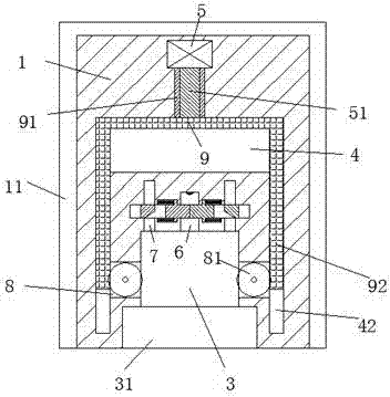
[0021] refer to Figure 1-6 The electric vehicle charging device shown includes a charging pile body 1 and a charging gun head 2 that penetrates into the charging pile body 1 and is connected. A chassis 11 is fixedly installed on the bottom of the charging pile body 1 . The bottom of 11 is provided with a sinking tank 12 with the port facing down. The counterweight iron block 13 is detachably installed in the sinking tank 12, and the counterweight iron block 13 is used to increase the stability of the charging pile body 1. The charging pile body 1 is provided with a clamping groove 31 with the port facing forward, and the rear end of the clamping...


PUM


Abstract

The invention discloses an electric vehicle charging device. The device comprises a charging pile body and a charging gun head which penetrates into the charging pile body and is connected with the charging pile body in a matched mode. A bottom plate is fixedly arranged at the bottom of the charging pile body, a countersunk groove with a downward opening is formed in the bottom of the bottom plate, and a counterweight iron block is detachably arranged in the countersunk groove; a clamping groove with a forward opening is formed in the charging pile body, and a penetrating groove communicated with the clamping groove is formed in the rear end of the clamping groove; a charging cavity communicated with the penetrating groove is formed in the rear end of the penetrating groove; control grooves communicated with the penetration groove are symmetrically formed in the positions, on the left side and the right side of the charging cavity, of the charging pile body; fastening devices used for fastening the charging cavity are symmetrically arranged on the positions, on the left side and the right side of the charging cavity, in the charging pile body. The device is simple in overall structure, power supply is safe and stable, overall operation is safe and reliable, electric shock accidents in existing life are effectively reduced, and the device is suitable for application and popularization.

Description

technical field [0001] The invention relates to the technical field of electric vehicles, in particular to an electric vehicle charging device. Background technique [0002] Due to the characteristics of energy saving and environmental protection of electric vehicles, low cost of use and low noise, the usage of electric vehicles is very high nowadays. Electric vehicles need to charge the batteries of electric vehicles before use, so the usage of charging piles for electric vehicles is also It is getting bigger and bigger, but the charging cavity in the existing charging pile body is always in the energized state, and the charging cavity is not equipped with a cover that can be covered, and it is easy to cause electric shock when plugging in the charging gun. If someone accidentally kicks the lock of the charging gun head and hits the cable by mistake, it will cause the charging to be interrupted and affect the normal charging. Contents of the invention [0003] The techni...

Claims


Application Information

Patent Timeline
IPC IPC(8): B60L11/18H01R13/629H01R13/639
CPCB60L53/16B60L53/31H01R13/62944H01R13/639Y02T10/70Y02T10/7072Y02T90/12Y02T90/14
Inventor 吴敏俊
Owner JIANGSU XIYI HIGH NEW DISTRICT TECH DEV CO LTD
Learn More